The Physics of the PV module.
(Seasoned electrical authorities having jurisdiction (AHJs) may skip the section.)
Photons (solar energy from sunlight) hit a PV module and electrons (electrical energy) come out. The amount of electricity (volts and amps) a PV module will produce is proportional to the amount of sunlight shining on the module (more is better), the module/cell temperature (cooler is better), and the electrical load placed on the module (just the right amount is best).
For code purposes, knowledge of the high and low expected local ambient temperatures is needed by both the PV designer and the AHJ. The amount of sunshine (called irradiance-a term for power, and irradiation-a term for energy) is needed by the PV system designer to determine the electrical power (watts) and the energy (watt-hours) that the PV module and the PV array can produce. Historical weather data will be used to determine the local irradiation and the temperature ranges.
The effect that these environmental factors have on the PV module performance and how the Code addresses these effects will be discussed in Part 2 of this article.
Are They Safe?
The National Electrical Code (NFPA 70) (NEC), requires that electrical installations and electrical equipment be examined for safety (90.7). This “examination for safety” is the responsibility of the AHJ, but few are fully qualified or equipped to perform detailed examinations on the electrical equipment being installed. Typically, the AHJ relies on a third party to examine the equipment and the use of listed equipment results.
Many different types of electrical equipment throughout the Code are specifically required to be “listed” and this means that the equipment has been tested by an independent Nationally Recognized Testing Laboratory (NRTL) that has been designated by OSHA as capable of listing a category of equipment against safety standards published by Underwriters Laboratories (UL) ( https://www.osha.gov/dts/otpca/nrtl/nrtllist.html). The listing process involves testing and certification that the product meets the requirements of standard after which, the product information is placed on a list maintained by the NRTL. Periodic retesting and inspections are conducted on the manufactured product at the end of the assembly line to ensure that the listing continues to remain valid. For the most part, although the tests are stringent and sometimes take weeks or months to complete, the UL standards are safety standards and do not verify long term product performance, reliability or durability.
Although the NEC does not specifically require that all electrical equipment be listed, the industries producing this equipment, including that used in PV systems, are manufacturing all types of equipment needed for electrical installations that has been listed to appropriate UL Standards. Many jurisdictions require that all equipment used in an electrical installation be listed, even where the NEC does not specifically require a listing.
The UL Standards are available for purchase, but are quite expensive (approaching $1000 each for a subscription which includes some updates). A detailed knowledge of the requirements in certain standards have caused AHJs to “red tag” PV installations where the equipment being installed obviously did not meet those requirements. This is usually due to an oversight by the NRTL applying the UL standards or in some cases where the requirements of the UL Standards are not clear or easily understood.
Even though NEC Section 90.7 exempts the wiring and materials internal to listed equipment from inspection by the AHJ, it pays to keep one’s eyes open for obvious failures in the production of that equipment that have resulted in safety concerns. See Scott Humphrey’s recent articles on the inspection of utility-scale PV systems in the IAEI magazine.
NEC Section 690.4(B) establishes that PV modules must be listed and several NRTLs are designated by OSHA to list those products. They each have marks (symbols) that will appear on the back of the PV module and include UL (Underwriters Laboratories), ETL (Intertek Testing Services NA, Inc. (ITSNA)), TUV (TUV Rheinland PTL, LCC), and CSA (CSA Group Testing and Certification, Inc.).
Many modules will also have a CE mark which indicates that a European self-certification has been conducted by the manufacturer against European IEC standards. The CE mark has no legal standing for meeting NEC listing requirements. However, some jurisdictions, in addition to requiring certification/listing of PV modules by a US NRTL using UL Standard 1703, are also requiring the CE Self-certification tests, which, in some cases, are more stringent than the UL Safety Standards and include performance testing.
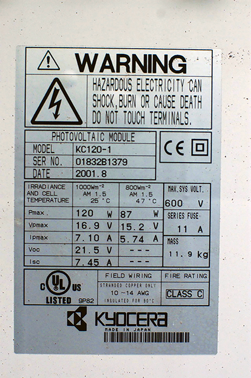
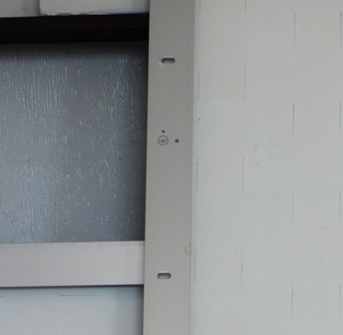
Not all PV modules are listed. There are PV modules being sold on the internet and through brick and mortar stores that are not listed. They may have the full technical details of the module printed on a label on the back, as would any fully listed module, and they may have the CE mark or other certification marks, but one of the four NRTL marks listed above will be missing (photo 1). Some PV module manufacturers have some of their product lines listed while other modules from the same manufacturer are not listed. The modules may be of the same size, so it is useful when there is any doubt to look for the listing mark. Each of the NRTLs maintains a full catalog of the products by manufacturer and model number that they list on their web site.
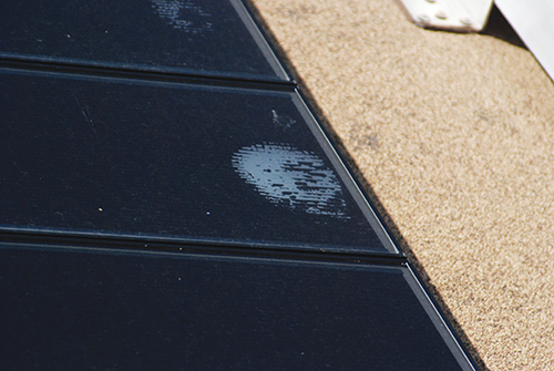
Damaged modules are not safe. While PV modules that are properly installed are robust and relatively immune from environmental damage, damage does occur in the installation and mounting of these modules. PV modules that have structural damage such as bent frames, cracked glass or damaged back sheets may not be safe and could create electric shock hazards or possibly arcing or ground faults that could result in fires (photo 2).
Such damage has resulted from mounting modules closely together side-by-side with no intervening space on a rack that is not of the same material as the module frames, such as a steel racking system. Aluminum framed PV modules expand at a certain rate as they get hot. Steel racking members expand at a different rate. When the modules are mounted tightly together side-by-side on the rack there is a possibility that the modules may be damaged due to the differential expansion of the two materials.
Mounting and Grounding.
Mounting. The instruction manual that comes with each PV module will show the acceptable methods of mounting and grounding the PV module. These methods that are shown have been evaluated through the listing process, and when followed should result in a module installation that is durable and safe.
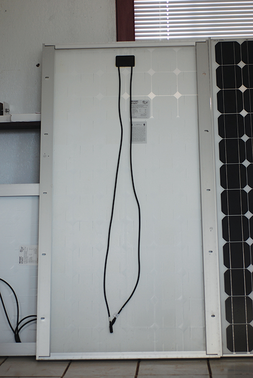
Historically, PV modules have had (and still do have) four to ten holes drilled in the rear of the frame that are used to mount the module to a structure (photo 3 and photo 3A). In the early days of photovoltaic power system installations, modules were mounted to various racking systems including wooden structures, steel galvanized racks and directly to a roofing surface using various locally obtained brackets or other mounting devices. The module instruction manual will establish how many of these mounting holes must be used to physically secure the module to the mounting structure. Wind loading tests during the certification/listing process have validated the module durability using these mounting instructions.
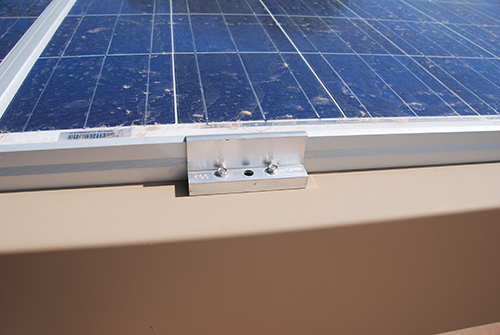
In more recent times, UL Standard 2703 (Standard for Mounting Systems, Mounting Devices, Clamping/Retention Devices, and Ground Lugs for Use with Flat-Plate Photovoltaic Modules and Panels) (https://standardscatalog.ul.com/standards/en/standard_2703_1) has been published that identifies racking systems that have used not only the holes drilled in the back of the module frame, but also various clips, clamping/retention devices and other devices that fasten the module to the rack in a secure and less time consuming manner (photo 4). Due to the significant variations in module frame dimensions and materials (including various coatings), now, the PV module instruction manual must at least show the areas where various clips may be used to mount the module on the frame and have been tested for that type of mounting during the listing process. And to be even more precise, the PV installation instructions may show which specific racking systems listed to UL 2703 have been evaluated with that module.
In a similar manner, a ranking system listed to UL Standard 2703 should have a list of all the modules that it has been tested with. As with the PV modules, the instructions for mounting those modules provided in the racking instruction manual should be followed.
There is an ongoing process to quantify the various shapes, sizes, materials, and coatings of PV module frames into a few categories. After this process is completed, it will not be necessary to test every possible module and rack combination during the listing process of each product. It will only be necessary for the rack manufacturers to test one of each type of module frame to evaluate the ability to mount all modules having frames of the same type. It will still be necessary, of course, to list the racking systems in the module instruction manual that have been evaluated for use with that module type, or at the very least designate the module type and the various racking systems that have been listed to mount that type of module.
Grounding. Two to six holes are also drilled and marked on the back of the module frame that are used to electrically ground the module (photo 3, 3A). Grounding the module, historically, was done by attaching some sort of listed grounding device to at least one of the marked grounding holes on the module and running a copper equipment grounding conductor between the various modules and finally along with the circuit conductors to the main system grounding point for the electrical power system. Listed grounding devices that were suitable for the outdoor environment and did not corrode were used for this purpose. In some cases, the module manufacturer provided specific hardware with the module to attach the copper conductor to the aluminum frame. It was and still is important to isolate the dissimilar metals of copper and aluminum from each other or galvanic corrosion will result eating away some of the aluminum and losing the electrical continuity of the grounding connection. There are some grounding devices that have been listed to UL Standard 467 (Grounding and Bonding of Equipment), but newer grounding devices for use in PV systems will be listed to UL Standard 2703.
The new racking systems include grounding devices that electrically connect and mechanically mount the PV module frame to the rack in a manner that does not use significant amounts of unnecessary hardware or labor. The various mechanical pieces of the racking system are electrically bonded together by design and when the PV modules are electrically bonded to the racking system, only one connection to the rack with a copper equipment grounding conductor will ground all the PV modules. Although the standard is published, details are still evolving on how all the various modules will be evaluated, certified, listed with all the various racking systems. Again, certifying the PV module as a specific mechanical “type” of module for grounding and bonding as well as mounting will simplify the procedure. That slow process is ongoing.
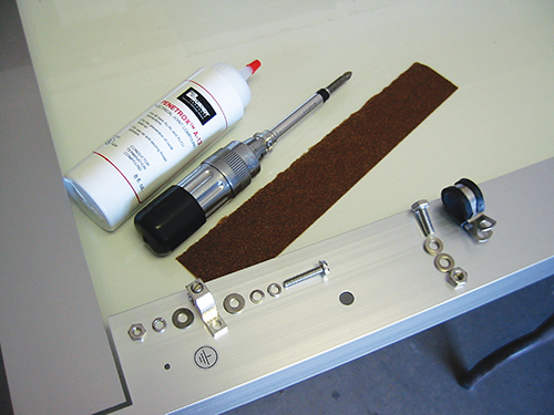
It should be noted that individual connections of equipment grounding conductors to each module it is still perfectly acceptable provided that the correct grounding/bonding device is used to make the connection (photo 5). In this case where the conductors are routed in air between the modules or between rows of modules, attention must be paid to the requirements NEC Section 690.46 which directs us to 250.120(C). And that section establishes that conductors routed in free air with little mechanical support or protection must be no smaller than 6 AWG.
Circuit Conductor Routing
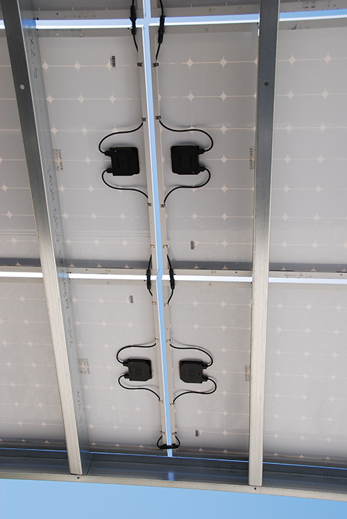
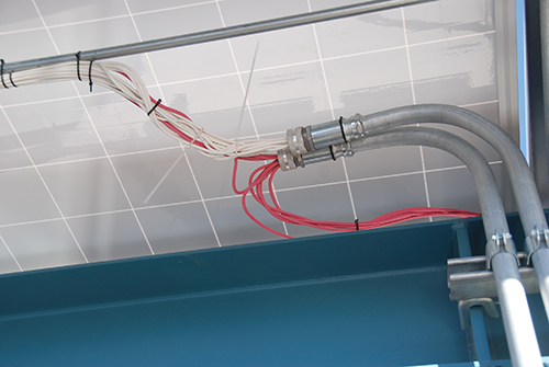
PV module output connections. Most PV modules come with attached single conductor output conductors that are approximately 4 feet long and are made of PV wire, a cable type specifically designed for use with PV systems. These conductors are sufficiently long to allow the modules to be mounted in either the portrait mode or the landscape mode without the use of any intervening extension cables between the series connected modules (photo 6).
It is desirable to secure the single conductor PV wire cables from each module in a manner that prevents them from moving under the severe outdoor environmental conditions for many years. Any unrestricted motion of these cables will put strains on the module connection points and allow for the possibility of abrasion of the insulation against structural module and rack members.
Unfortunately, 690.31(C)(1) requires that the PV wire be installed in accordance with 338.10(B)(4)(b) and 334.30. These sections refer to the installation of jacketed cables in indoor installations and impose unrealistic distances on the fastening of the PV wire. For example, 334.30 requires that the PV wire be secured within 12 inches of any outlet box which would include the module junction box. When modules are installed in the landscape mode, the two connecting cables may be too short to meet this requirement. Adding an extension cable to the two existing module output conductors would require an additional connector pair and create an additional reliability point. In other cases, the module junction box is not within 12 inches of the module frame and the requirement cannot be met. These requirements are being re-examined for the 2020 NEC but that is some years away.
A more realistic and enforceable requirement would be that the module PV wire output cables be secured to the nearest structural member along the most direct method of routing between modules that can be achieved for that module orientation. Excess cables should be secured to the structural members with clips or mechanical fasteners that do not deter-iorate over time.
It is probably not adequate to rely on a “sunlight resistant” cable attachment device to secure PV wires for 40 to 50 years (photo 7). The sunlight resistance label refers to an accelerated ultraviolent test of 720 hours which is equivalent to about a year and half of sunlight exposure in the desert Southwest. Metal clips or straps or combinations of those devices with rubber insulators should be considered (photo 8).
Connectors, Connectors, Connectors-A Potential Long-Term Safety Hazard
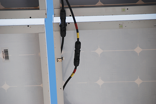
In the early days of PV systems, modules had junction boxes with internal terminal strips for the input/output connections. The modules were wired from module junction box to module junction box using USE-2 single conductor cables. As PV systems became more popular, the PV modules sold in the US were equipped with single conductor cables permanently attached to the module junction boxes with connectors on the ends; a trend started in Europe. Multi-Contact was one of the first manufacturers of PV connectors and they made a product called the MC3 connector which could be pulled apart. It was not a locking connector. That connector was followed by the MC4 connector that is a locking connector that requires a tool to open and meets the requirements of 690.33(C). Multi-Contact was followed by a few other connector manufacturers such as Amphenol who made unique series of connectors that were not compatible with the Multi-Contact connectors.
As the number of module manufactures world-wide grew, connectors started show up on modules that were advertised to be compatible with the MC4 connector, but were not actually made by Multi-Contact. While these connectors appeared to be like the MC4 connector and appeared to be electrically and mechanically compatible, there was a major issue. The new connectors had never been tested and evaluated with Multi-Contact MC4 connectors through the strenuous listing process by an NRTL using the PV connector standard UL 6703.
Connector manufacturers guard the actual materials used in the manufacture of the connectors zealously. The actual alloys used in the metallic electrical contacts and the actual chemical makeup of the plastics used are not advertised or available throughout the industry. Slight variations in the materials used to make the plastic parts of the connectors can result in differing thermal expansion and create the potential for intrusion of moisture. The alloys used for the electrical contact surfaces or the coatings on those contact surfaces are critical to the long-term durability of the electrical connection in the outdoor PV environment. Daily thermal cycling and moisture intrusion due to sunlight and current flow can create chemical reactions between various alloys resulting in galvanic corrosion which may result in contact deterioration and possible sparking. Over time, the connector may lose the ability to mate properly with the connector made by another manufacturer. At least one connector pair failure has been reported between MC4 type connectors made by two different manufacturers.
This situation will inevitably get worse as more and more modules are installed with mismatched connectors from different manufacturers. It is generally not possible to evaluate connectors from different manufacturers against each other during a field inspection because such testing and listing would require a continuous and expensive testing and monitoring process as the two manufacturers involved made small, possibly unadvertised or unannounced, changes in the mechanical, chemical and materials properties of their individual connectors.
More Information Coming.
UL Standard 1703 has been modified to require that either the instruction manual or the label on the back of the PV module specify the manufacturer and the product series number of the connectors being used on that module. There will also be a warning statement in the instruction manual that the listing on the module will become invalid if connectors from other manufacturers are used in the installation of the module. Information and warnings of a similar nature will also appear in UL 6703 the connector standard. Violating the listing on a PV module will also violate the Code requirements (110.3(B)).
As mentioned in a previous article in this series, an attempt is being made to develop a production/manufacturing standard for PV module connectors. Such a standard would differ from the UL 6703 safety standard in that it would specify the materials, the mechanical configuration, the alloys, and the tolerances for manufacturing a PV connector. When the standard is published, all module manufacturers would hopefully adopt this standard and have connectors made that would meet this standard. Then the connector would be listed against this new manufacturing standard as well as against the safety requirements of UL 6703.
There is some reluctance in the PV module industry to work on the standard due to the widespread use of certain connectors, and we also have an issue with finding a standards writing body like NEMA (National Electrical Manufacturers Association) that could develop the standard, publish it and maintain it. It may take a few fires and pressure from the Fire Service and the insurance industries to get this connector standard developed.
Summary
Residential, commercial and utility scale PV systems are being installed in increasing numbers. The power generating device in these installations is the photovoltaic (PV) module and that module is continuing to evolve in size and power output. There are also variations in the basic materials from which it is manufactured. The AHJ must have a firm basic knowledge of how the PV module works and how it should be installed to comply with the requirements of the NEC. The installation requirements and the methods of meeting these requirements are changing as new technologies are developed for module racking, module grounding and module mounting. In the next article in this series we will discuss how the outdoor environment affects the output of the PV module and how the code is written to accommodate these output variations.
For More Information
The author has retired from the Southwest Technology Development Institute at New Mexico State University, but is devoting about 25% of his time to PV activities to keep involved in writing these “Perspectives on PV’ articles in the IAEI News and to stay active in the NEC and UL Standards development process. Seven to eight hour presentations are still available on PV and the Code and they cover 2011-2017 NEC requirements. He can be reached at: e-mail: jwiles@nmsu.edu, phone: 575-646-6105
The Southwest Technology Development Institute web site maintains a PV Systems Inspector/Installer Checklist and all copies of the previous “Perspectives on PV” articles for easy downloading. A color copy of the latest version (1.93) of the 150-page, Photovoltaic Power Systems and the 2005 National Electrical Code: Suggested Practices, written by the author, may be downloaded from this web site: https://swtdi.nmsu.edu/codes-standards/