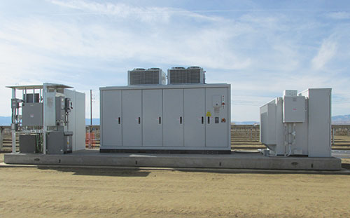
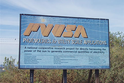
Almost ten years ago, I had the pleasure of working on and testing new concept inverters for a large manufacturer at a facility called PVUSA (Photovoltaics for Utility Systems Applications). PVUSA was built in 1986 by PG&E (sponsored by the DOE and private industry) and was one of the first test facilities for this emerging technology (see photos 2A & B). This joint partnership was an effort to study PV operational characteristics in a utility system, and to ascertain confidence in predicting PV performance, reliability and the economic life of PV. Or, to put it bluntly, would it be beneficial to invest in this new technology called Photovoltaics? This test facility is where the first large-scale inverters were tested, such as Helionetics, Omnion and Blue-Point Dickerson in the range of 25 kW to 275 kW. These inverters experienced ongoing issues with startup, voltage imbalances, ground fault trips, sequencing, and synchronization, to name a few.
In 1991, one of many reports regarding islanding (or inverter run-on) was published describing how some inverters continued to export power to the grid when the grid power was removed and how this event could create a safety hazard for utility line crews performing repair or maintenance work. Some of these tests detailed events that continued to export power (after the grid was removed) for over 11 minutes and it was theorized that, under certain conditions, some had the tendency to run-on indefinitely. The standard used at the time was IEEE 1035-1989 (Test Procedure for Utility-Interconnected Static Power Converters) and, based on the aforementioned discovery regarding islanding, new anti-islanding concepts were presented by the Central Research Institute of Electric Power Industry (Japan), Arizona State University and others to address these safety concerns.
INDUSTRY ABBREVIATIONS
- AHJ Authority Having Jurisdiction
- FRT Fault ride through
- IBC International Building Code
- ICC-ES International Code Council–Evaluation Service
- IEEE Institute of Electrical and Electronics Engineers
- LVRT Low-voltage ride through
- NRTL Nationally Recognized Testing Laboratory
- PG&E Pacific Gas and Electric Company
- PVUSA Photovoltaics for Utility Scale Applications
- UVRT Under-voltage ride through
Based on those past safety concerns during those early years of development, two standards were developed, including IEEE 1547 (Standard for Interconnecting Distributed Resources with Electric Power Systems) and UL 1741 (Standard for Inverters, Converters, Controllers and Interconnection System Equipment for Use with Distributed Energy Resources). Technology has certainly come a long way since those early years, and we now deal with inverters on equipment skids/shelters that consist of an assembly of components such as:
- one to four-megawatt inverters (operating at 1000 v to 1500 v DC)
- 35 kV step-up transformers
- step-down transformers at various voltages
- large DC disconnects
- large DC re-combiners
- combiner curtailment controls
- manual transfer switches
- AC panelboards
- busways
- fiber optic patch panels
- wire-ways
- weather stations
- tracker controllers
- security systems with microwave communication
This is a partial list of what you may encounter; remember, this technology is advancing daily as new products are introduced to enhance efficiency and energy production. Additionally, these large scale inverters are different from the more common residential and commercial products, in that during voltage swings or other anomalies, these inverters are capable of riding through the event. This capability is commonly called low-voltage ride through (LVRT), or fault ride through (FRT), or under-voltage ride through (UVRT) and is used to avoid a short circuit on the high voltage level which could cause widespread power outage or a chain reaction with multiple generators going offline.
This article will focus on some of the challenges of turnkey inverters, assembly of components, installation pitfalls, and basic codes/standards required for compliance.
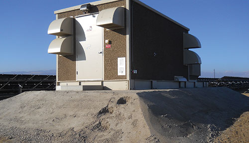
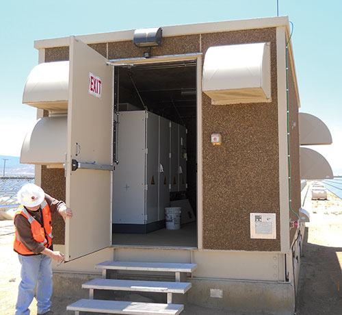
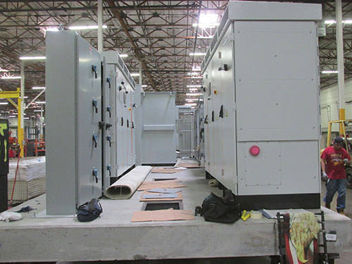
Equipment Shelters
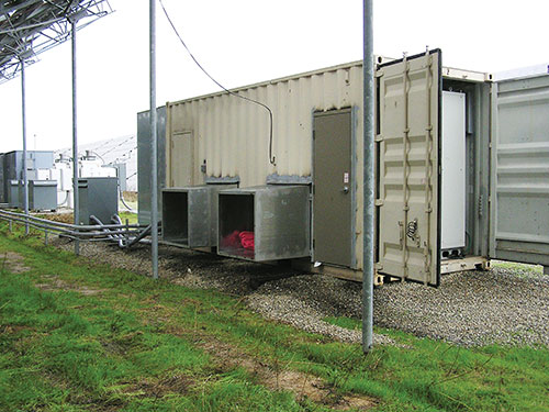
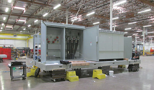
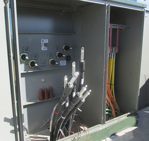
Equipment shelters (see photo 3A) are used at these large-scale projects when the equipment is rated for indoor use, TYPE-1, and/or where weather conditions make performing maintenance and commissioning operations undesirable. One common issue here is achieving proper working space for the 1000/1500 volt inverters. If the inverters inside the enclosure are installed facing each other [condition 3 Table 110.34(A)], the distances between the equipment will be required to be greater than if the equipment is mounted only on one side of the enclosure [condition 2 Table 110.34(A)].
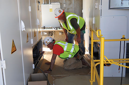
I have seen both types of installation, and it can get cramped inside these shelters (see photo 3B). These enclosures (or buildings) will have additional step-down transformers for lighting, control circuits, smoke detectors, and ventilation. A common issue found here is the improper use of fine-stranded conductors (see photos 4A & B). Remember, these equipment shelters are assembled at some other location, possibly out of state, and typically unskilled labor is used to build, assemble, and wire the components. Because of this, many NEC code violations may be encountered. Some common issues found include:
- inverters are not NRTL listed
- certified vcombiner curtailment controls are listed/certified to the incorrect UL Standard
- required markings missing for
- arc-flash hazard warning
- manufacturer’s markings (main nameplate missing)
- field applied hazard markings
- disconnecting means
- available fault current
- drawings do not match the installation
- panelboards contain the incorrect breakers
- installation manual does not provide appropriate information for field supplied terminations
- depth of working space is not sufficient
- heat exchanger and controls are not NRTL listed/certified
- ventilation and lighting controls are not NRTL listed/certified
- DC feeders entering the inverters (from the vault) do not have proper strain relief
- cable trays are overfilled
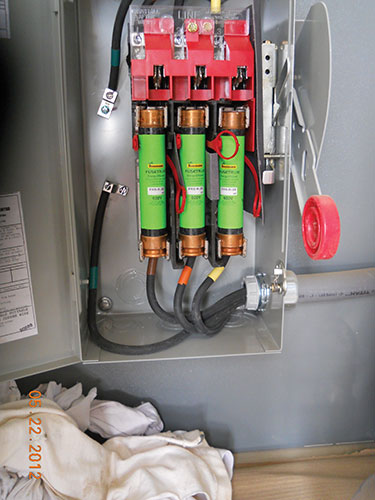
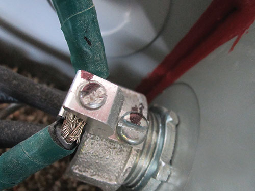
Photos 4A & B. Fine stranded DOL cable used for general wiring.
These are just a few of the most common issues encountered. Something to keep an eye out for is that some equipment shelters/skids may arrive with a state certification that may or may not be acceptable to the AHJ. I mention this because at several projects I have encountered situations where the nameplate, certified by the State, did not provide a complete list of components installed in or around the shelter. This lack of a component list raised a red flag; and after further discussions with the independent third party, it was discovered that they only viewed the building (structure) and one 7.5 kV transformer and one 240-volt panelboard. The 35 kV transformer, 1000 v inverters, 1000 v controls, etc., were never inspected but did have a State certification stating the 1.5-megawatt platform was compliant.
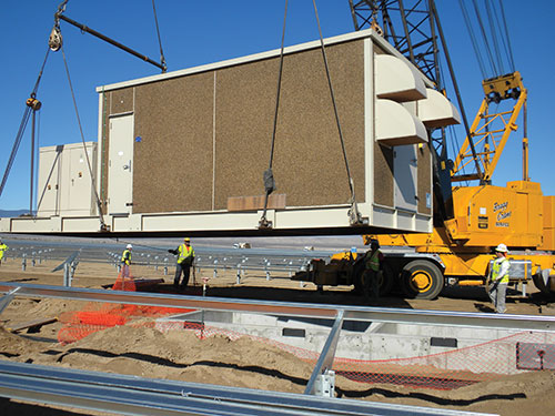
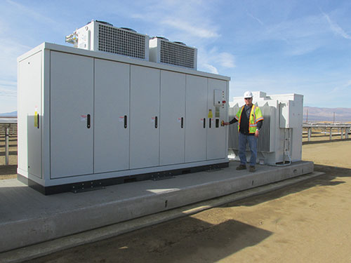
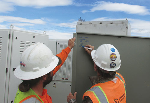
Some manufacturers (and assemblers) of these multi-megawatt platforms are listing/certifying these buildings through field evaluations at the factory or the final destination (see photo 5). This flexibility can be a useful tool for the installing contractor and the AHJ in achieving some level of compliance. However, make sure you are involved at the beginning of the project to ensure that all of the appropriate standards are used during the evaluation. At a recent project, the supplier had already had the assembly certified. However, the NRTL used the incorrect standard(s) during the evaluation and many other standards were not used. Additionally, the design changed over a short period and the components originally evaluated (inverters, 35 kV transformers, 2000-amp DC disconnects) were now all different in kVA, current, new busways, etc. Because this technology is constantly evolving, the manufacturers and NRTLs may not understand and/or apply the codes and standards correctly. Alternatively, they are not able to keep up with design changes, which is why the AHJs need to review the equipment to the approved drawings and ensure the main nameplate has captured all the appropriate information (see photo 6).
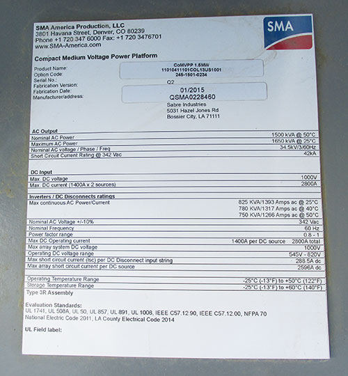
Some things to look for on a main nameplate are:
- product name
- serial number
- fabrication version
- fabrication date
- manufacturer/address
- AC output
- Nominal AC Power (given in kVA @ what Celsius)
- Maximum AC Power (given in kVA @ what Celsius)
- Nominal AC Voltage/Phase/Frequency
- Short Circuit Current Rating @ Vac
- DC input
- DC voltage
- DC Current (and how many sources)
- Inverters/DC disconnects rating
- continuous AC power/current (given in KVA/Amps @ 25c, 40c, 50c)
- Nominal AC voltage +/-10%
- Nominal Frequency
- Power factor range
- DC operating current
- array system DC voltage
- Operating DC voltage range
- short circuit current (Isc) per DC disconnect input string
- array short circuit current per DC source
- Operating temperature range
- Storage temperature range
- Type rating (assembly)
- Evaluation standards (most common)
- UL 1741
- UL 508A
- UL 50
- UL 857
- UL 891
- UL 1008
- IEEE C57.12.90
- IEEE C57.12.00
- NFPA 70 2014
- NRTL marking
As you can see, it is a little more involved than the standard main nameplate based on all of the different components, voltages, and currents and how they interact with each other. If you’re not getting this minimum information on your equipment, this should be a “red alert” that requires more involvement by your inspection team to determine the appropriate plan of action. Additionally, these projects take several months to several years to complete, so be aware. Just because you had a code-compliant installation for the first set of shelters (a few months back), some designs change, or maybe everything changes and, hopefully, the NRTL(s), manufacturer(s), assembler(s), and you (AHJ) were involved with that change.
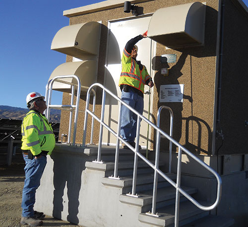
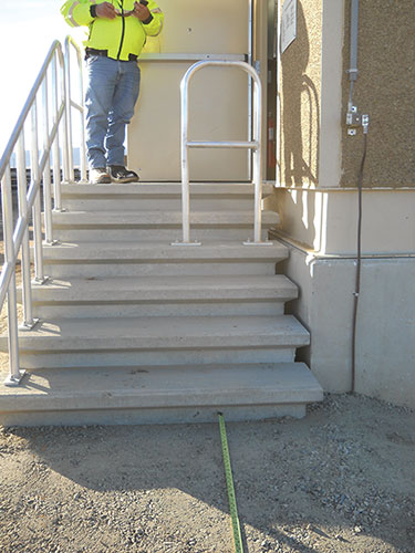
Another common issue with these projects is the access/egress from the equipment in the form of stairs or steps (see photos 7A, B, C, D, E). These buildings are not occupied structures so disabled access requirements of the International Building Code (IBC) are usually not applied. Some of the common issues encountered are as follows:
- Landing at doors (length) in the direction of travel do not meet IBC Section 1008.1.6EX (36 inches)
- Landing at bottom of stairs is absent and is not the width of the stair (IBC Section 1009.8)
- Headroom at stairs is less than 80 inches (minimum clearance shall be maintained the full width of the stairway and landing IBC 1009.5)
- Stairway requires handrails on both sides (IBC Section 1009.15)
- Handrail height is less than 34 inches (IBC Section 1012.2)
- Guards are required around equipment walking surfaces that are located:
- more than 30 inches high, measured vertically to grade below
- at any point within 36 inches horizontally to the edge of the open side (IBC Section 1013.2)
- Guards are less than 42 inches high (IBC Section 1013.3)
- Guards have openings greater than 21 inches (IBC Section 1013.4EX-3)
- Door swings over a step (IBC 1008.1.5)
This is just a partial list of IBC deficiencies encountered. These are imperative since most of the servicing and/or maintenance occurs during the evening with limited lighting when the arrays are not producing. Not enforcing these requirements could be a recipe for a fall and/or tripping hazards that can be avoided by applying the minimum requirements of the IBC.
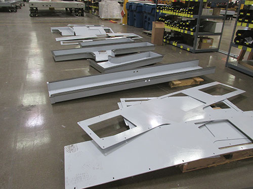
Equipment Skids
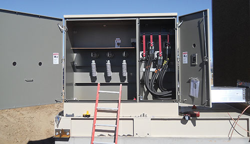
Equipment skids are an assembly of the aforementioned equipment attached to a high-strength steel support structure (skid) or high strength concrete precast pad (skid) (see photo 8A, B, C, D, E, F). All of the components are now exposed to the weather and all components, conduit systems, wire-ways, busways, etc., shall be verified to the appropriate type ratings for the location. Again, this equipment will arrive pre-assembled. Hopefully, the assembler implemented a third-party review acceptable to the AHJ. Over the years, I have reviewed 355 equipment skids/shelters — some arrived with some form of certification while others did not. In each case, something always changed during the different phases of construction. It could be something as simple as a change to the control transformer. Alternatively, it could be something more critical, such as a manufacturer inverter change or a cable bus replaced with busways. Communication and hands-on involvement at the site is critical to avoid project delays, equipment modifications, and angry project leaders. By identifying early on an issue with a design change that the contractor was unaware of at the start of the project, you can help project leaders avoid many headaches.
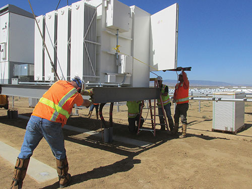
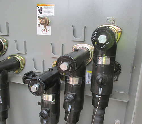
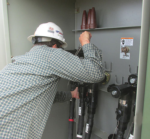
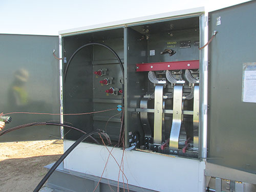
The equipment skids (as stated in the shelter section) should have a main nameplate acceptable to the AHJ indicating all the appropriate voltages, currents, ratings, etc. The list of required elements is too long for this article; and as technology advances, these values may change as your project progresses so you’ll need to look up the requirements with each review/inspection. And stay alert — if the design has changed drastically, is the system now producing more power? And is the engineer aware of the implications and cascading effect this additional current could have (on the feeders, relay settings, etc) to the substation and/or utility? This is part of the reason inspections are so important! During your inspections, have the electricians open up all of the equipment, or be present during all field terminations to save time and expedite the inspection process (see photo 9A, B, C).
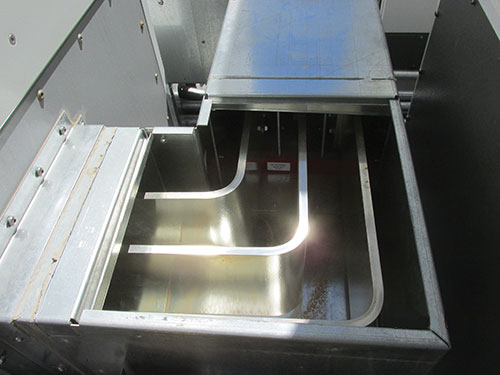
This will give you the opportunity to check all equipment to the approved design. As an example, at one recent project the contractor had an approved design (equipment skid) that arrived NRTL certified for the assembly of components. During the review/inspection of the construction evaluation report, several changes in the design were found. The inverters had different kW ratings, the transformer ratings changed, and the DC disconnects ratings changed, which can change the input and output characteristics of the equipment. Additionally, upon checking clearances for flexible and fixed busway supports (see photo 10A & B), it was found that some supports were absent and some clearances through free air were not maintained. After further discussions with the manufacturer, it was discovered that months earlier a ground fault had occurred with similar equipment, but only one busway was remediated with an extra support. No one looked at the second busway where the clearance of 1 inch to grounded parts was not verified by the original manufacturer or NRTL. My point here is always verify the assembly (it’s ok to look inside the box, you are encouraged to look inside equipment) and don’t stop at field terminations. You might discover a deficiency that was overlooked by several professionals and could save the owner from unscheduled events and lost revenue. As stated in the UL 857-7.1.2.1.3.1 Standard, “The clearance and creepage distances in a short run busway shall be no less than those indicated in Table-8 (one inch).” Section 7.1.1.47 says “short run busway insulating supports for bus shall be spaced no more than 24 inches apart as measured between centers of adjacent supports along the length of busway.” Additionally, busbars in busways are required to be braced based on the short-circuit current rating (SCCR). Table 16 of UL 857 Standard may require shorter distances than 24 inches so contact a qualified NRTL to further discuss and ensure a safe installation.
Some other common issues encountered are as follows:
- Improper working space around equipment
- Improper clearance around control transformers
- EMT fittings are not outdoor rated
- Equipment protection is absent
- Switches are over the maximum allowed (6 ft, 7in.)
- Main nameplate does not match current installation
- Some/all NEC warning labels and/or equipment labels are absent
- Fine stranded conductors terminated under unlisted set screw terminations
- 35kV BOL-T components are a mix of copper and aluminum (pending event)
- 35kV high-press lug is one size too large
- A307 bolts used at 35 kV terminations (grade 5 required)
- Some DC feeder terminations are loose
- Inverters are not listed/certified by a recognized NRTL
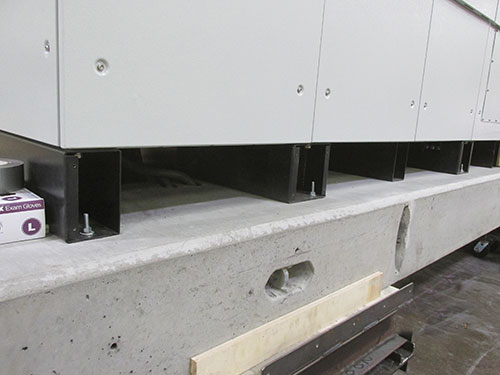
- Fabricated 7000 psi concrete vaults were never verified by special inspection (SI) (IBC Chapter 17)
- Structural welding for attachment of skid to steel imbeds requires SI
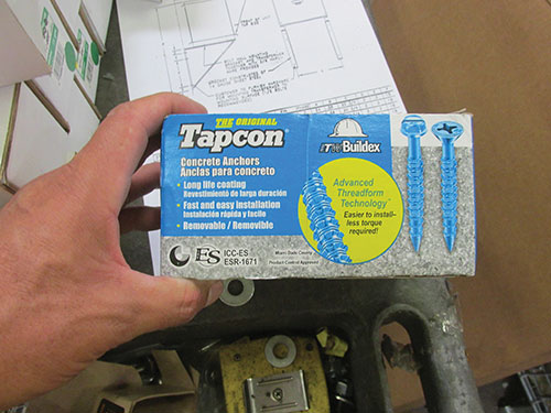
- All post installed concrete anchors require SI
- For shelter to vault attachment
- For equipment attachment
- Drawings do not match installation
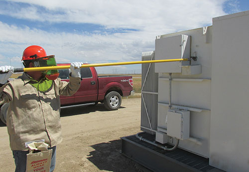
This is a partial list of what you may encounter at these projects; and, remember, you will have thousands of connections to verify (electrical and structural). Depending on the velocity of the project, you may need to dedicate several inspectors to ensure a safe, code-compliant installation. Additionally, there is one more thing to keep in mind regarding worker safety at these sites: knowing how the operator performs proper lock-out/tag-out/tryout and how they operate the equipment is imperative and could save a life. On many occasions, I have had to deploy to the field with the design engineers to demonstrate how the equipment is properly operated (see photo 11).
Summary
I did dive into some of the micro details of the IBC requirements; but please remember, Chapter 17 still applies for these fabricated shelters/skids for high-strength concrete, structural steel, and welding. And don’t forget that the medium/high-voltage terminations used at these sites are not NRTL listed/certified and, depending on your comfort level and inspection experience, you may want to require verification by a qualified NRTL.
These equipment shelters/skids provide unique challenges for manufacturers, assemblers, NRTL(s), and AHJs when it comes to applying appropriate codes and standards, inspecting all of the equipment, working with this new and ever-evolving technology and educating the local installer working at these multi-megawatt projects. A thorough review by your structural/electrical department(s) and appropriately detailed inspections will pay dividends (literally) in ensuring a safe, code-compliant installation that will operate efficiently for decades with limited maintenance and/or unscheduled events.
I would like to close this article with a quote from the 1987 book Uncommon Friends by James D. Newton, where he describes a 1931 conversation between Thomas Edison and his friends, Harvey Firestone and Henry Ford:
“I’d put my money on the sun and solar energy. What a source of power! I hope we don’t have to wait ‘til oil and coal run out before we tackle that.”