Traditionally, the electrical system design engineer has given little attention to the elevator controller. In fact, an entire elevator system for a project is most often designed and specified by the architect who has little understanding of the electrical distribution system. Because of this, there is often a communications gap between the electrical system designer, whose design typically stops at the required elevator disconnecting means, and the architect who designs the elevator system. To address this issue, Code Making Panel (CMP) 12 of the National Electrical Code® acted on several proposed changes to Article 620 during the revision cycle for the 2017 NEC that deal with the proper installation of elevator controllers.
The proposals resulted in adding new requirements in the 2017 NEC for:
- Marking the elevator controller short-circuit current rating (SCCR) by the elevator controller manufacturer.
- Reinforcing NEC3(B) and NEC 110.10 to require the elevator controller marked SCCR to be equal to or greater than the calculated and marked available short-circuit (fault) current at the elevator controller.
- Marking the available short-circuit (fault) current on the controller by the equipment installer.
This article will also discuss other Code requirements that include selective coordination for elevators that are supplied by emergency, legally required standby or critical operation power systems or multiple elevators supplied from a single feeder, and shunt tripping of elevators where the elevator equipment room and/or shaft has a fire suppression sprinkler system. Finally, typical installations and compliance with all these requirements will be discussed.
Equipment SCCR and short-circuit current marking requirements
The reason the NEC CMP 12 added these requirements, as shown in the panel statements, directly relates to the concern that elevator controllers can be installed in locations where the available fault current can be high and the inspector may not be able to clearly determine the SCCR of the elevator controller unless it is marked on the equipment. The panel further clarified that the marked SCCR value must be adequate for the available fault current to ensure a safe installation. In order to aid enforcement, the panel additionally required marking the available fault current at the elevator controller. Below is a summary of these new 2017 NEC sections:
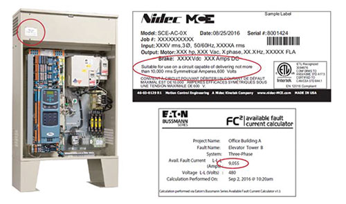
- 620.16(A) Manufacturers must mark their elevator control panels with an equipment short-circuit current rating (SCCR). The SCCR can be based on an assembly product standard listing and labeling, or an approved analysis method, such as UL 508A, Supplement SB.
- 620.16(B) If the elevator control panel SCCR is not equal to or greater than the available fault current, the elevator control panel must not be installed.
- 620.51(D)(2) An elevator control panel must now be field marked with the maximum available fault current along with the date the calculation was made. Further, if there is a change to the available fault current, then this field marking must be revised.
Complying with these new requirements
In order to comply with these requirements a chain of events must occur.
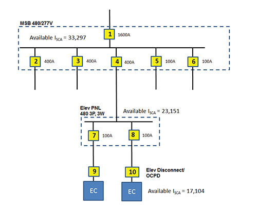
- The electrical system designer calculates the maximum available fault current at the elevator controller.
- The electrical system designer needs to communicate this information to the person responsible for specifying the elevator controller, which is most often the architect.
- The party responsible for procuring the elevator control panel must state the minimum acceptable SCCR or the maximum available fault current where the controller will be installed.
- The elevator controller manufacturer must determine the required elevator controller SCCR as stated in the elevator controller specification and provide an elevator controller SCCR that is equal to or greater than the available fault current that’s indicated in the design documents where there are multiple elevator controllers at different locations.
With these new NEC requirements, there is now the potential that an elevator controller SCCR may be required that’s higher than what elevator manufacturers have historically furnished. As such, elevator controller manufacturers should make the effort to rethink their designs to avoid costly system design changes. For instance, a typical elevator controller may traditionally have SCCR ratings from 5 to 10 kA. However, it is likely that for many elevator controllers, this may not be high enough for the available fault current where they will eventually be installed.
Some elevator controller manufacturers believe this is an issue for the electrical system designer and installer to address and remedy by adding impedance to the system for lowering the available fault current. This, however, can result in a dramatic increase in cost, space availability (lack thereof), and reduced efficiency. For instance, one method to reduce the available fault current is to add an isolation transformer ahead of the elevator controller.
Many new buildings are incorporating an elevator design that does not include an equipment room (sometimes called machine room-less elevators). All equipment in a machine room-less design is installed within the elevator shaft or exterior compartment near the elevator shaft, including the elevator controller and the elevator disconnecting means. In these installations, it is best to design the elevator controller so the elevator controller SCCR is adequate for the available fault current. This is something that can be easily accomplished if the elevator controller manufacturer uses components in combination with overcurrent protective devices that are tested and listed with high combination SCCRs. In many cases, the overcurrent protective devices that are suitable for this level of protection are current-limiting fuses rather than a traditional circuit breaker. In this case, it may be best if the elevator controller manufacturer does not include the elevator disconnecting means (often offered as a circuit breaker) but instead have the installer provide a separate fused disconnect to comply with NEC 620.51(A) and also achieve a high SCCR for the elevator controller when fuses are provided as specified by the elevator controller and marked on the elevator controller nameplate.
Selective Coordination
If elevators are supplied by the emergency, legally required standby or critical operation power systems, then selective coordination is required per the 2017 NEC in 700.32, 701.27 or 708.54. Selective coordination is also required for multiple elevators per NEC 620.62. Another important electrical system design consideration for supplying power to multiple elevators is NEC 620.62. NEC 620.62 requires the elevator disconnecting means (fused switch or circuit breaker) to selectively coordinate with all supply-side overcurrent devices. Selective coordination is defined by the NEC as: “Localization of an overcurrent condition to restrict outages to the circuit or equipment affected, accomplished by the selection and installation of overcurrent protective devices and their ratings or settings for the full range of available overcurrents, from overload to the maximum available fault current, and for the full range of overcurrent protective device opening times associated with those overcurrents.”
In order to comply, the electrical system designer must determine the maximum available fault current at the elevator disconnecting means and assure the elevator disconnecting means overcurrent protective device will clear any overcurrent condition, up to the maximum available fault current, before any upstream overcurrent devices will operate. Notice the definition mentions the full range of operating times. This is important as the tradition of using only time-current curves for the analysis of overcurrent device operation is usually not sufficient since the time-current curves traditionally stop at 0.01 second (not time “zero”).


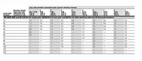
For current-limiting fuses, the information to achieve selective coordination has been available for many years in fuse amp ratio tabular form. These selective coordination tables for current-limiting fuses show the minimum amp ratio required between a pair of fuses of a given type(s) to achieve selective coordination.
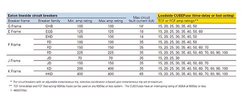
For circuit breakers, time-current curves must be consulted as well as the circuit breaker manufacturer’s selective coordination tables. These circuit breaker selective coordination tables can be used to identify the maximum fault current that a pair of circuit breakers can selectively coordinate. It is important to note, that these selective coordination tables can indicate a lack of selective coordination at a given fault current for circuit breakers that do not show overlap on the time-current curves of the circuit breakers. For some manufacturers, such as Eaton, testing has been completed to determine the selective coordination ability of current-limiting BussmannTM series fuses with upstream Eaton circuit breakers.
Shunt Tripping
Where the elevator shaft and/or equipment room has a sprinkler fire suppression system installed, the elevator Code requires main line power to the elevator be removed prior to the application of water. This is typically accomplished via a shunt trip device.
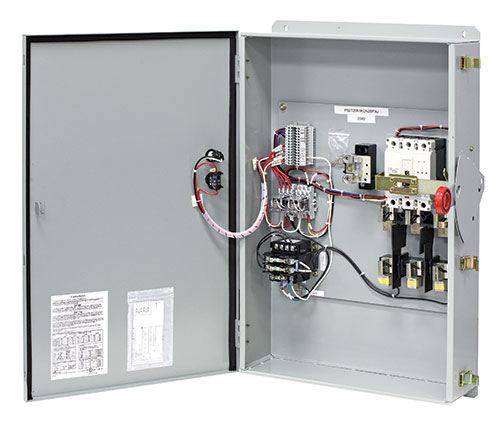
There are options available to achieve this depending upon the customer’s needs. The simplest option is to use a shunt trip circuit breaker in either the feeder supplying the elevator or the elevator disconnect. For elevators with battery lowering systems, an additional contact must be supplied and wired to disable the battery lowering system when the elevator disconnect is manually operated for maintenance. NFPA 72 requires the control circuit between the Fire Alarm System and the shunt trip be monitored for integrity. In addition, the shunt-trip voltage must also be monitored by the Fire Alarm System. Loss of voltage to the control circuit for the disconnecting means shall cause a supervisory signal to be indicated at the control unit and required remote annunciation. In some cases, it may require a means to test the shunt trip operation or have one contact operate the shunt trip of more than one elevator. Per the 2017 NEC, if the elevator is designated as an emergency system load, the disconnect must be protected by a surge protective device (SPD). All of these options and special wiring can be challenging depending upon the location of the shunt trip circuit breaker as well as who has responsibility for providing these additional options. Because of this, several manufacturers offer an all-in-one shunt trip elevator disconnect switch that includes all the prewired accessories needed to comply with the various Code sections.
Typical Elevator Installations
The architect has a choice of either traction or hydraulic elevators. Traction elevators are typically faster and more energy efficient than hydraulic elevators, and are often used for high-rise buildings. Hydraulic elevators are typically more cost effective and used for buildings up to 5-6 stories. Traction elevators are typically installed in a “bank of elevators” where fused switches, or circuit breakers in a panelboard are located in the machine room serving the bank of elevators. Each fused switch or circuit breaker in the panelboard is used as an elevator disconnect. Hydraulic elevator installations are typically supplied from the main switchboard and have an elevator fused switch or circuit breaker in the machine room that serves as the elevator disconnect.
As mentioned, traditional installations of a traction or hydraulic elevator include a separate machine room. The vast majority of equipment serving the elevator is located within this room (i.e., elevator controller). Also located in this room might be, but not limited to: exhaust fan, cooling unit (depending on local requirements and/or requirements set forth by the individual elevator supplier), lighting, voice and/or data drop serving the elevator cab emergency phone, elevator controller primary fused disconnect, elevator feeder shunt-trip circuit (i.e., shunt-trip circuit breaker), elevator cab lighting fused switch, and convenience receptacle(s).
Machine room-less elevator installations incorporate the elevator controller and often the primary disconnecting means in a convenient package that is located within the elevator shaft. However, space is frequently limited within the shaft and as such many ancillary components (shunt trip circuit breakers, fused disconnects) may need to be located outside of the elevator shaft. It is important for design engineers to communicate this with the architect and owner during the design phase, as it will impact space needs elsewhere in the facility to accommodate electrical equipment.
A traditional elevator installation (which includes a machine room) requires access inside the elevator shaft. Convenience receptacles and lighting for maintenance purposes are required at the base of the pit and, in some instances (elevator manufacturer dependent), at the top of the elevator shaft. It is important for the design engineer to coordinate with the architect to determine the elevator manufacturer basis of design to determine if and when additional power and lighting is required.
It is of great importance for the design engineer to communicate with their local authority having jurisdiction (AHJ) to determine fire alarm requirements for the respective elevator installation. While machine room-less designs have been commercially available for many years, their use may still be unknown to some AHJs. Design practices that are acceptable in some jurisdictions may not be in others. As always, the best advice in all instances…do your homework, communicate often, and document decisions made. Years may lapse between the design and installation stages of a project. Good documentation is of key importance to recalling what decisions were made and why.
Summary
With the new elevator controller requirements, more attention will be focused on the elevator system. First, it is now clear that elevator controllers must be marked by the manufacturer with their SCCR. The design engineer must identify the available fault current at the elevator controller to the installer so an elevator controller with adequate SCCR can be provided. If this is not done and the available fault current exceeds the elevator controller SCCR, other solutions to reduce fault current must be reviewed or equipment changes and field evaluations may be needed. In addition, requirements for selective coordination and shunt tripping should be complied with as needed for the installation.
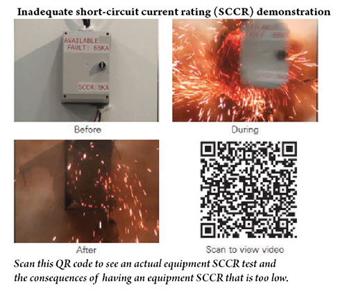
What are the Safety Hazards of Inadequate SCC
The hazards are external to the equipment enclosure since equipment SCCR testing and evaluation criteria for product standards are most often performed with the enclosure doors closed and latched, and the fault occurring external to the enclosure. Installing electrical equipment where its SCCR is less than the available short-circuit current creates serious safety hazards. These may include:
- Shock: The enclosure becomes energized from conductors pulling out of their terminations or device destruction occurring within the enclosure.
- Fire: The explosive power of the internal devices failing causes the closed and latched door to become ajar and spew flame and molten metal to the exterior. This is a fire hazard to both the facility and personnel.
- Projectile (shrapnel): The enclosure door may blow open or off with fire and failing device debris (shrapnel) shooting out. In laboratory tests, equipment SCCR failures have resulted in enclosure doors explosively blowing off and flying up to 100 feet away. Additionally, the shrapnel, from the rapid failure of internal devices, can be ejected at speeds up to 700 miles per hour.
The author would like to recognize Jonathan Kennedy for his assistance in creating this article.