Zone-selective interlocking (ZSI) has been in practical use since the mid-1980s. This technology was created to speed up the tripping time for some faults within a zone of protection without sacrificing selective coordination and interjecting nuisance tripping into the system. The advantage of quickly being able to open circuit breakers during a short circuit or ground fault is a reduction of incident energy and all of the heat and stresses that these events place on electrical distribution equipment. The zone of protection for a ZSI system includes the area between two zone-selectively connected overcurrent devices.
The concept of zone-selective interlocking is common in utility applications and discussed in Institute of Electrical and Electronic Engineers (IEEE) papers even as early as the 1930s. The general concept is to provide a method to change the reaction of an overcurrent protective device based on where the fault occurs in the system. This provides the ability of an overcurrent device to respond differently once it has a general idea of where the fault is located. This was important to the utilities in the early 1900s to solve problems regarding stability and reliability.
The journey and advancements in electronics made it possible to put microprocessors and integrated circuits into small packages. As digital electronic technologies advanced, the first molded case circuit breaker to have a solid-state trip unit was introduced in 1969. This new device was called the Systems Circuit Breaker. The technology provided ground-fault protection of equipment (GFPE) and short-time delay capabilities. It was 1972 when Westinghouse introduced the Seltronic circuit breaker which was designed to be interchangeable with existing thermal magnetic circuit breakers of the same size frame. The time-current characteristic (TCC) curves were very similar but provided improved coordination through the addition of short-time delay functionality. It was 1974 that GFPE was added in response to GFPE National Electrical Code (NEC) requirements of section 230.95 for service entrance equipment.
The journey of technology within power circuit breakers (PCB), insulated-case circuit breakers (ICCB), and molded-case circuit breakers (MCCB) has continued to grow, bringing new advancements in electronics to a wide range of applications providing solutions that give increased levels of protection. GFPE, GFCI, and AFCI technology are good examples of the benefits this technology brought to the industry over time.
What is ZSI
Zone-selective interlocking is a method that allows pairs of circuit breakers or relays to identify that a fault occurred within a zone of protection and clear that fault by the circuit breaker directly upstream of the event opening without an intentional delay.
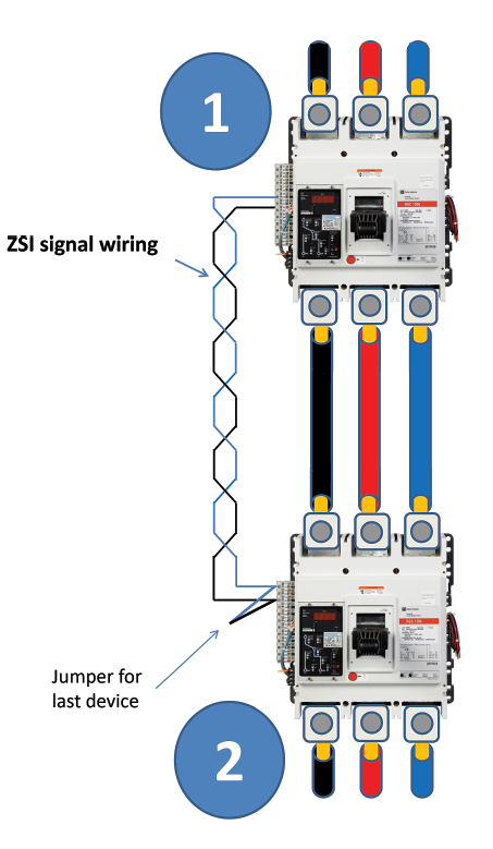
This is achieved when two circuit breakers are wired together via a signaling wire. As shown in Figure 1, the downstream circuit breaker (2), through these signaling wires, has the ability to let the upstream circuit breaker (1) know when it sees a fault current that exceeds its short-time pickup (STPU) setting. The upstream circuit breaker looks for a voltage presence on the signaling wire when fault currents exceed its STPU setting and makes a decision to either wait to open based on its programmed settings or ignore those settings and trip without an intentional delay. Whether this upstream device decides to wait, or trip immediately, is dependent on whether the upstream device sees a signal on that signal wire or does not.
The zone of protection in Figure 1 lies between devices 1 and 2. Any fault between the secondary terminals of device 1 and the primary terminals of device 2 will cause device 1 to trip without an intentional delay because device 2 will not have sent a signal over the ZSI signal wire as it does not see the fault current flowing. Any fault downstream of device 2 will result in both devices 1 and 2 responding as per their TCC curve and physical settings on each circuit breaker.
The physical connection between these two devices is a small gauge twisted pair. Examples of wiring sizes that you may find being used to interconnect two circuit breakers or relays together to create a ZSI installation are 16 AWG, 18 AWG, 20 AWG, or 24 AWG. Shielding is not required, but also not prohibited. Note that the specifics of wire sizes and other details may be dependent on individual manufacturer solutions. This technology is not one that can tolerate multiple manufacturers being connected together. There are also other limitations involved that will probably vary by manufacturer, including the maximum length of twisted pair between two devices and maximum number of connected devices to an input or output terminal, as well. These limitations are due to the need of maintaining signal strength and voltage at the ZSI input terminals of the devices.
There are ways to extend the distance between two devices when following manufacturer guidelines. The installation instructions, as usual, must always be followed for proper installation and application. The two devices shown in Figure 1 may both be in the same enclosure with device 1 being the main and device 2 being a feeder or branch breaker within the panelboard. The two devices shown in Figure 1 could also be in two different enclosures with device 1 being a feeder circuit breaker in one panel and device 2 being the main circuit breaker of another panel. The zones of protection for both of these examples are different.
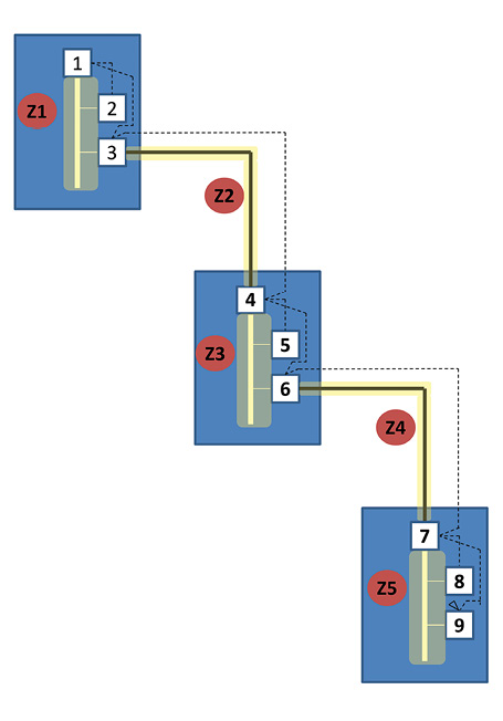
The installation could have more than one zone of protection by having a series of panels connected as shown in Figure 2. The zones of protection shown in Figure 2 are as follows:
Zone 1 (Z1): Established by connecting circuit breaker 1 with downstream circuit breakers 2 and 3. The protection afforded is that bus between the main circuit breaker (device 1) and all branch/feeder circuit breakers in the panel (devices 2 and 3).
Zone 2 (Z2): Established by connecting circuit breaker 3 with circuit breaker 4. The protection afforded is for that length of conductor between both panels.
Zone 3 (Z3): Established in the same manner as zone 1 by connecting circuit breaker 4 with downstream circuit breakers 5 and 6. The protection afforded is the panelboard bus between the main circuit breaker (4) and all branch/feeder circuit breakers in the panel (devices 5 and 6 in this case.)
Zone 4 (Z4): Established by connecting circuit breaker 6 with circuit breaker 4. The protection afforded is for that length of conductor between both panels.
Zone 5 (Z5): Established by connecting circuit breaker 7 with downstream circuit breakers 8 and 9. The protection afforded is the panelboard bus between the main circuit breaker (7) and all branch/feeder circuit breakers in the panel (devices 8 and 9).
ZSI and incident energy reduction
Equipment protection is the primary focus of this technology. When the upstream device knows where the fault is (if in the right zone), it can ignore the programmed delays, and incident energy reduction is the result. This faster response time translates into less energy, resulting in less damage to the equipment.
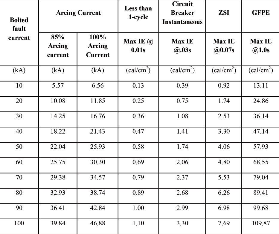
Figure 3 illustrates a table of incident energy calculations based on the clearing times of the various technologies on the market. The bolted fault current values range from 10 kA through 100 kA and the associated arcing currents and incident energy values calculated as per IEEE 1584-2002.
ZSI and selective coordination
The challenge in those systems that leverage selective coordination is the longer delay times that upstream circuit breakers must employ to achieve selectivity. The increased delay times of an upstream device necessary to permit downstream devices the time to clear fault currents results in higher incident energy.
Zone-selective interlocking is a method to reduce equipment damage without losing the benefits of selective coordination. When a fault occurs downstream, outside of the zone of protection, the paired devices that are zone-selectively interlocked know to trip per their programmed settings. They will respond as per their TCC curves and per the selective coordination design, leaving the downstream device closest to the fault the job of clearing the fault, thus achieving selective coordination.
Zone-selective interlocking has no negative impact on selective coordination and is always on the job. However, ZSI does not give selective coordination. If the devices are not selectively coordinated for the amount of fault current flowing in the system, ZSI won’t make them selectively coordinate.
ZSI the NEC and inspection
Prior to 2011, zone-selective interlocking was not a part of the National Electrical Code (NEC). ZSI was a technology that many industrials purchased to provide protection for equipment. NEC 2011 introduced 240.87, which was titled “Non-instantaneous Trip,” but is now titled “Arc Energy Reduction,” and ZSI was one of the technologies used to address the problem of incident energy. The challenge with ZSI is that there is no external indication to let anyone know that ZSI is employed and ready to respond. Drawings will indicate the wiring, and a physical look in the box for the wires will help awareness. However, when things are all buttoned up, external indicators are not present.
NEC 2020, as of this writing, is considering field testing of these technologies to ensure they are connected and functioning. The arcing current has to be greater than the settings that activate these technologies. So, primary injection testing is the only real way to ensure the system is functioning as a system. As per the above, the installation can have more than one downstream circuit breaker or relay tied into the ZSI system, and there could be more than one upstream circuit breaker or relay creating quite a complex system.
Trained professionals can perform tests to ensure these systems are working as needed. Hopefully, NEC 2020 will include field verification at installation, so a report can be provided not only to the authority having jurisdiction (AHJ) but also to the owner and others in need of this important information.
Zone-selective interlocking is a technology that has been around for quite some time, leveraged by many installations of the years. NEC 2011 includes the first introduction of this technology. It is the protective equipment through faster clearing times when a fault occurs in the zone of protection. Engineers, installers, inspectors, and owners must understand the capabilities and limitations to ensure expectations are achieved. Zone-selective interlocking is a great technology that hopefully will see more applications as an effective means to protect equipment.