The currents in a PV system are somewhat different from the currents traveling through a typical alternating current (ac) electrical system. Yes, the PV system has ac circuits and they are somewhat like a typical ac load circuit, but the direct current (dc) circuits are a little unusual. This article will address the unique aspects of these dc currents and how the Code handles them.
Current Sources
While PV modules produce volts, amps, and watts, they are considered to be current sources and operate differently than the normal voltage sources commonly experienced in the 120/240-volt ac circuits in our homes or the 12-volt dc circuits in our automobiles.
A voltage source can have very high available short-circuit currents. If it were not for the overcurrent devices in the load centers and main disconnects, the typical utility transformer feeding a residence could deliver short-circuit currents approaching 10,000 amps. The larger transformers feeding commercial buildings with 480-volt ac can deliver even higher short-circuit currents. The typical 12-volt automotive battery can send several thousands of amps into a short circuit.
PV modules as current-limited current sources have a limited capability to produce high currents. A typical 208-W PV module might have an operating current of 7.5 amps and be able to deliver a short-circuit current of only 8.1 amps. The amount of current a single PV module can deliver is limited by the size of the cells in the module, the method of internal wiring, and the brightness of the sunlight falling on it.
Modules are rated in the laboratory at a set of standard test conditions (STC) that include, among other things, a standard sunlight (solar) intensity of 1000 watts per square meter (W/m2). At 1000 W/m2, the module is tested and the values of short-circuit current (Isc), and operating current (Imp) are recorded. Average production values for these two parameters are marked on the back of the module along with other items. On most modules, the short-circuit current at STC will be only about 10–15% higher than the operating current.
When modules are connected in series to form what the PV installer calls a “string” of modules, the operating and short-circuit currents do not change. The string currents are the same as the values for a single module. However, the voltage that each module produces does add up in the string and many typical residential PV systems operate with voltages in the 400- to 600-volt range.
A 480-Volt PV System is NOT like a 480-Volt Feeder
As the PV systems get larger (commercial systems), the operating voltages will usually be limited to no more than 600 volts, except in a few experimental systems operated by utilities on utility property and behind secure utility fences. But, as the system size and power increase, the current will increase above the few tens of amps into hundreds of amps. There are now single, utility-interactive inverters rated at 500 kW ac output and they will have dc operating currents and short-circuit currents at the inverter input approaching 1000 amps (see photo 2). These large PV systems, and the high levels of dc current, while not as large as the
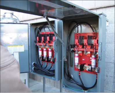
Photo 2. High-current dc fusing
hundreds of thousands of amps associated with 480-volt ac feeders, must be treated with extreme caution when working on such a system when energized (see photo 3).
Fortunately, most residential PV systems rated at power levels of 2500–5000 watts have dc currents in the 5–15 amp range and are proportionately less dangerous from an arcing point of view.
Working Safely on PV Arrays
With a solar energy source, it is somewhat difficult to turn off the current from an illuminated PV module. If the attached leads from each module were available, they could be disconnected (open circuited) or connected together (short-circuited) to reduce either the current or the voltage from the module to zero. However, in most PV systems, these leads and their connectors are not readily accessible, so other means must be used to work on active systems. One method is to cover the modules with an opaque surface, but this is rarely

Photo 3. 250 kW inverters
done on any but the smallest systems. The area of a PV array in a typical residential PV system might be hundreds of square feet as shown in photo 4.
In the typical PV module, the output conductors are terminated in connectors that are insulated and are, to a limited extent, considered “touch safe”— photo 5. These connectors can be plugged together safely, and, in the usual wiring sequence, at least one pair of these connectors is left open until all other wiring is done on the PV array. By leaving one connection open in each string of the array while making terminal connections to disconnects at the end of each string, the possibility of getting shocked is somewhat reduced. However, ground faults and stray leakage currents can always present a shock hazard, so insulated gloves and tools are recommended when making terminal connections.
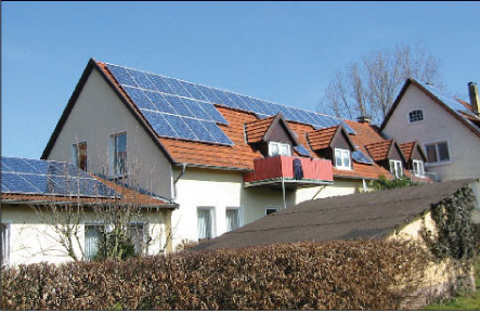
Photo 4. Residential rooftop PV array
Continuous Currents
From the onset, the PV Industry has been aware of the nature of the PV module as a current source, the limited nature of that current, and its relationship to the intensity of the solar radiation. Article 690 of the National Electrical Code was written to address this unique nature of the PV module and the PV system. Several requirements are in the Code that will allow PV systems to be safely designed and installed in a manner that should provide an essentially hazard-free system for the life of the PV module—a life that may approach 50 years.
For purposes of calculating the ampacity of conductors, the Code requires that the rated dc short-circuit current (not the operating current) from a single PV module or the current from a combiner box that carries the paralleled output of several strings of modules be multiplied by 125 percent [690.8(A)]. This 125 percent factor is applied to address the fact that the solar irradiance on clear days in many parts of the country may exceed the standard test condition value of 1000 W/m2 by a varying amount. Values of 1150 W/m2 (115 percent) are not uncommon for periods that can last three hours or more. This 125 percent factor ensures that on a continuous basis (as defined by the NEC), the currents used in ampacity calculations are the worst possible currents that could be generated by the PV module. Also, by this calculation, we are implying that these currents exist continuously 24 hours per day when, actually, they will never reach the 125 percent level, may only be above 1000 W/m2 for only a few minutes each day, are lower most of the time, and drop to zero at night. Also note that the calculation involves the short-circuit current, not the operating current which is typically 10–15% lower, and that the short-circuit current would normally only flow under a fault condition.
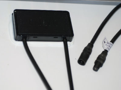
Photo 5. “Touch Safe” module connectors
Then, the normal Code provision (applied to all conductors and most overcurrent devices) is added where they must have a basic ampacity of 125% of the continuous load (already 125% of Isc) [690.8(B)]. Since this is an energy supply system, we use the term source currents rather than load currents, but the same calculations apply. The Code has now required that a 156 percent (125% x 125%) factor be applied to the rated short-circuit current for the module or modules. This ensures that, after appropriate corrections have been made for conditions of use, the conductors carrying the dc currents from PV modules will never be overloaded and will be operated within their ratings for the life of the system.
Conservative Designs Yield Long, Safe Operation
PV modules may be producing hazardous voltages and currents for 40 years or longer. Using the 156% factor on the short-circuit current to size cables and rate overcurrent devices helps to ensure that these devices will safely and reliably carry the normal PV currents for many years. Even in the extreme outdoor environment (hot, wet, and ultraviolet) that provides challenging operating conditions, conservative ratings keep conductors and overcurrent devices well within their operating tolerances.
For Additional Information
If this article has raised questions, do not hesitate to contact the author by phone or e-mail. E-mail: jwiles@nmsu.edu Phone: 505-646-6105
A color copy of the latest version (1.6) of the 150-page, Photovoltaic Power Systems and the 2005 National Electrical Code: Suggested Practices, published by Sandia National Laboratories and written by the author, may be downloaded from this web site: http://www.nmsu.edu/~tdi/Photovoltaics/Codes-Stds/PVnecSugPrac.htm
The Southwest Technology Development Institute web site maintains a PV Systems Inspector/Installer Checklist and all copies of the previous “Perspectives on PV” articles for easy downloading. Copies of “Code Corner” written by the author and published in Home Power Magazine over the last 10 years are also available on this web site: http://www.nmsu.edu/~tdi/Photovoltaics/Codes-Stds/Codes-Stds.htm
The author makes 6–8 hour presentations on “PV Systems and the NEC” to groups of 40 or more inspectors, electricians, electrical contractors, and PV professionals for a very nominal cost on an as-requested basis. A schedule of future presentations can be found on the SWTDI web site.