Symptom
The machine does not start when the start button is pressed.
At this point, the problem could be mechanical or electrical. We will focus on just the electrical circuit faults for now. This fault could be located in either the power circuit or the control circuit. The fault could also be many different types, such as, open-circuit fault, short-circuit fault or a ground fault.
This general troubleshooting procedure is designed to start in the middle of the problem area and give us the best idea of which direction to go. The control transformer is a good place to start since it is in the middle of the circuit and is part of the power and control circuits.
The first three steps of this procedure will be the same for all faults and the rest will be completed throughout this chapter in more than one procedure. There is no one procedure that can guide you through any given problem. For simplicity’s sake, we will now take one area and one type of fault at a time. The first fault we will investigate is the open-circuit fault.
We will now investigate open circuit faults in the control circuit.
Open-Circuit Faults in the Control Circuit
Open-circuit faults – An open circuit fault is any fault that stops the operation of a machine due to an open wire or component. Let’s develop our procedure for troubleshooting an open circuit in the control circuit. Remember that the first three steps will be the same for all faults.
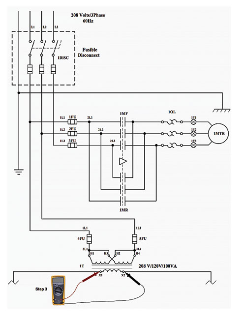
Step 1. You must analyze the schematic diagram for a general circuit overview.
[Proper personal protective equipment must be worn when working on energized equipment.]
Step 2. You must carefully open the control panel with power energized since voltage checks will need to be made. [The operation of the voltmeter and proper rating should have been verified efore continuing.]
Step 3. You should check the voltage at the X1 and X2 terminals at the secondary of the control transformer.
If correct voltage is not present, then the problem is in the power circuit.
If correct voltage is present and the contactor is energized, then the problem is in the power circuit.
If correct voltage is present, the contactor is not energized and the OL is not tripped, then the problem is in the control circuit.
Scenario: What’s happening?
Scenario is the motor does not start when the start button is pressed. The correct voltage is present at X1 and X2, the contactor is not energized and the OL is not tripped, then the problem is in the control circuit. For this scenario, the fault is an open-circuit fault and inside the panel. From the schematic in figure 1, you should have read 120 volts at terminals X1 and X2.
Since the correct voltage is present, we must troubleshoot the system in a logical order until we lose the correct voltage.
If the voltage changes from a good reading on one device to a different reading on the next device in logical order, then the device or wire in between those readings is open.
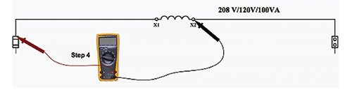
Step 4. You should check the voltage on X1 at the top of the control circuit fuse and X2 terminal at the secondary of the control transformer.
- If the correct voltage is present, continue to Step 5.
- If the correct voltage is not present, then X1 wire is open from the top of the fuse to the terminal on the secondary of the transformer.
You should check the voltage on X1 at the top of the control circuit fuse and X2 terminal at the secondary of the control transformer.
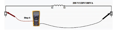
Step 5. You should check the voltage on X1 at the top of the control circuit fuse and X2 at the top of the neutral link.
- If the correct voltage is present, continue to Step 6.
- If the correct voltage is not present, then X2 wire is open from the top of the neutral link to the terminal on the secondary of the transformer.
You should check the voltage on X1 at the top of the control circuit fuse and X2 at the top of the neutral link.
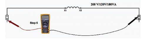
Step 6. You should check the voltage on wire #1 at the bottom of the control fuse and X2 at the top of the neutral link.
- If the correct voltage is present, continue to Step 7.
- If the correct voltage is not present, then the control fuse is open.
If the fuse is open, then there is either a short circuit or ground fault. If the fuse is not open, then there is an open-circuit fault. This is our first indication that the fault is an open-circuit fault.
You should check the voltage on wire #1 at the bottom of the control fuse and X2 at the top of the neutral link.
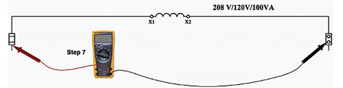
Step 7. You should check the voltage on wire #1 at the bottom of the control fuse and wire #2 on the bottom of the neutral link.
- If the correct voltage is present, continue to Step 8.
- If the correct voltage is not present, then the neutral link is open.
You should check the voltage on wire #1 at the bottom of the control fuse and wire #2 on the bottom of the neutral link.
Use the schematic diagram in Figure 5 as an illustration for Scenario A, assuming that we don’t know the location of the fault.
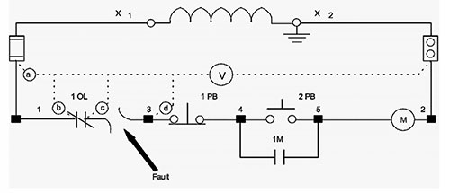
Step 8. Since the voltage at point a (bottom of the fuse) is the correct voltage, we will use wire #2 as our reference. We will make our measurements from left to right and then top to bottom until we find the voltage not present.
If the correct voltage is present, continue to Step 9.
Step 9. Check the voltage at point b (left side of 1OL) with wire #2 as a reference.
If the correct voltage is present, continue to Step 10.
- If the correct voltage is not present, then wire #1 is open from the bottom of the fuse to the left of the normally closed contacts for 1OL.
Step 10. Check the voltage at point c (right side of 1OL) with wire #2 as a reference.
- If the correct voltage is present, continue to Step 11.
- If the correct voltage is not present, then 1OL normally closed contacts are open.
Step 11. Check the voltage at point d (top of terminal #3) with wire #2 as a reference.
- If the correct voltage is present, continue to Step 12.
- If the correct voltage is not present, then wire #3 is open between the right side of 1OL and the top of #3 terminal.
SOLUTION OF THE PROBLEM
The fault is between the point where the voltage is present and the point at which it is not present anymore.
Reference:
Electrical Theory, Technology, PLC Concepts and Basic Electronics – Michelin North America, Inc.