Definition

Figure 1. Grounding electrode
Grounding electrode.
A conducting element used to connect electrical systems and/or equipment to the earth. [See figure 1]
General
For many applications, grounding electrodes provide the essential function of connecting the electrical system to the earth. The earth is considered to be at zero potential. In some cases, the grounding electrode serves to ground the electrical system. In other instances, the electrode is used to connect noncurrent carrying metallic portions of electrical equipment to the earth. In both situations, the primary purpose of the grounding electrode is to maintain the electrical equipment at the earth potential present at the grounding electrode.
Another essential function of the grounding electrode is to dissipate over-voltages into the earth. These over-voltages can be caused by high-voltage conductors being accidentally connected to the lower-voltage system such as by a failure in a transformer or by an overhead conductor dropping on the lower-voltage conductor. Over-voltages can also be caused from lightning.
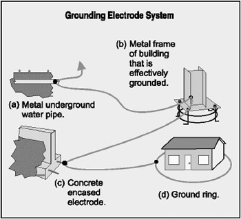
Figure 3. Grounding Electrode System
In Section 250-24(c), we find a requirement to connect the equipment grounding conductors, the service-equipment enclosures, and where the system is grounded, the grounded service conductor to a grounding electrode. The conductor used to make this connection is the grounding electrode conductor.
Grounding electrode system
The NEC in Section 250-50 requires that, where available on the premises at each building or structure served, all grounding electrodes including “made” electrodes be bonded together to form the grounding electrode system. This includes metal underground water pipes, metal frames of buildings, concrete-encased electrodes, and ground rings. The general requirement is that a bonding jumper must be installed between the grounding electrodes to bond them together. A grounding electrode conductor is run from the service enclosure to one of the grounding electrodes that are bonded together. The NEC also provides for the option of running a grounding electrode conductor to each grounding electrode individually. [See figure 3]
Where the interior metal water pipe is used as a part of the grounding electrode system or as a conductor to bond other electrodes together to create the “grounding electrode system,” Section 250-50 requires that all bonding take place within the first 5 feet from the point the water pipe enters the building. This section does not require that the interior water pipe be used for the purpose of interconnecting other electrodes to form the grounding electrode system. Any of the other electrodes, such as the metal frame of the building, concrete encased electrode or ground ring, can be used for the purpose of interconnecting the other grounding electrodes. Where these other electrodes are used for this purpose, no restrictions are placed on where the connections are permitted to be made or how far inside the building they are permitted. Section 250-68(a) requires grounding electrode conductor connections to grounding electrodes to be accessible except for connections to a buried, driven, or concrete encased electrode.
Grounding electrodes required to be used

Figure 4. Grounding electrodes that must be used
All of the identified grounding electrodes are required to be used where “available on the premises at each building or structure served.” The Code does not define what is meant by “available” nor does it require that the electrodes be made available where they are not. For example, if the building has encased concrete reinforcing rods when the electrical system is installed, it is not required that the rods be exposed for connection. On the other hand, the concrete reinforcing rods must always be used when “available.” Several electrical inspection agencies require that a concrete-encased grounding electrode be connected to the system before approval of the service for utility connection is granted. The grounding electrodes are not listed in an order of preference nor is it optional to choose which ones to use. [See figure 4]
Electrodes that must be used, in addition to any “made” electrodes that exist or are installed at the building or structure served, where “available” are as follows:
1. Metal Underground Water Pipe.Defined in Section 250-50(a) as “A metal underground water pipe that is in direct contact with the earth for 10 feet or more including any metal well casing that is effectively bonded to the pipe.” There is no minimum or maximum pipe size given. Types of metal, such as steel, iron, cast iron, stainless steel or even aluminum are not distinguished. Different types of water pipes such as for potable water, fire protection sprinkler systems, irrigation piping, etc., are also not defined. As a result, all of these metal underground water pipes must be used where “available at each building or structure served.”
Continuity of the grounding path of the water pipe grounding electrode or the bonding of interior piping systems cannot depend on water meters or on filtering devices or similar equipment. See Section 250-50(a)(1). Where a water meter or filtering equipment is in this metal water piping system, a bonding jumper must be installed around the equipment to maintain continuity even if the water meter or filter is removed.
2. Metal Frame of the Building.Section 250-50(b) requires the metal frame of the building to be used as a grounding electrode where it is effectively grounded. “Grounded effectively” is defined in Article 100 and means that the metal frame of the building is, “Intentionally connected to earth through a ground connection or connections of sufficiently low impedance and having sufficient current-carrying capacity to prevent the buildup of voltages that may result in undue hazards to connected equipment or to persons.”N

Figure 5.
To be an effective grounding electrode, the metal frame of the building must have a sufficiently low-impedance contact with the earth to pass current when called upon to do so and to maintain the electrical system at or near the electrical potential of the surrounding earth. The building steel can be connected to the earth by bolted or welded connection to reinforcing steel in foundations or footings that are in turn encased in concrete. Also, building structural steel may itself be encased in concrete that is in contact with the earth. In both of these cases, the concrete that encases the building steel or reinforcing steel must be in direct contact with the earth.
Certain back-fills such as gravel or vapor barriers may render the building steel an ineffective electrode. Building steel that is connected to concrete footings or foundations by only “J” bolts are not considered “effectively grounded” unless these “J” bolts are in turn connected to structural members such as reinforcing steel. The reinforcing steel needs to be near the base of the footing or foundation.

Figure 6. Size of bonding jumper for grounding electrode system
The structural steel should be tested with an earth resistance tester if in doubt about its resistance to ground and adequacy as a grounding electrode.
3. Concrete-Encased Electrodes.Section 250-50(c) defines this grounding electrode as one or more steel reinforcing bars or rods that are not less than 20 feet in length and ½ inch in diameter or 20 feet or more of bare copper conductor not smaller than No. 4. These electrodes must be located within or near the bottom of the foundation or footing and be encased by at least 2 inches of concrete. A single 20 ft. length of reinforcing bar is not required. Reinforcing bars are permitted to be bonded together by the usual steel tie wires or other effective means like welding. Where subjected to high currents such as lightning strikes, welding is preferred.
Reinforcing rods must be of bare, zinc galvanized or other electrically conductive coated steel material. Obviously, insulated reinforcement rods would not perform properly as a grounding electrode. Some complaints have been made that lightning surges, that are dissipated through this electrode, break out chunks of concrete where the surge exits the footing.
This grounding electrode is commonly referred to as the “Ufer ground” after H.G. Ufer who spent many years documenting its effectiveness. Additional information on the development and history of the concrete-encased electrode is available in the Appendix of Soares Book on Grounding.
Several electrical inspection agencies require that a concrete-encased electrode be installed or connected to the service prior to authorizing electrical service due to its effectiveness in most any climatic and soil condition.
4. Ground Ring.Section 250-50(d) recognizes a copper conductor, not smaller than No. 2 and at least 20 feet long, as a ground ring grounding electrode. The conductor must “encircle” the building or structure and be buried not less than 2½ feet deep. Ground rings often are installed at telecommunication central offices, radio and cellular telephone sites. Where available on the premises served, ground rings must be used as one or more of the grounding electrodes making up the grounding electrode system.
Supplemental electrode

Figure 7. Size of individual grounding electrode conductor
Section 250-50(a)(2) requires that where the only grounding electrode available and connected at the building or structure served is a metal underground water pipe, it be supplemented by another grounding electrode. Electrodes suitable to supplement the metal underground water pipe include: the metal frame of the building, a concrete-encased electrode, ground ring, other local metal underground systems or structures, rod and pipe electrodes, or plate electrodes. This supplemental grounding electrode is required since, often, metal underground water pipes are replaced by plastic water services or the system continuity is interrupted by nonmetallic couplings or repairs. The effectiveness of the water pipe grounding electrode would thus be lost.
Specific locations are provided where the supplemental grounding electrode is permitted to be connected. Where an underground metal water pipe is the only grounding electrode, the supplemental grounding electrode is permitted to be connected to only the grounding electrode conductor, the grounded service-entrance conductor, the grounded service raceway or to any grounded service enclosure. An exception to this requirement permits the bonding connection to the interior metal water piping in a qualifying industrial or commercial plant to be made at any location if the entire length of interior metal water pipe that is being used as a conductor is exposed.

Figure 8. Made electrodes
Often, changes, repairs or modifications are made to the metallic water piping systems with nonmetallic pipe or fittings or dielectric unions. In this case, it is possible to inadvertently isolate portions of the grounding system from the grounding electrode conductor. This is another in several steps that has been taken over recent years to reduce the emphasis and reliance on the metal water piping system for grounding of electrical systems.
With a change to the 1999 NEC, where the supplemental grounding electrode is of the rod, pipe or plate type, it is now required to meet the 25-ohm-to-ground rule in Section 250-56. This means that the supplemental grounding electrode must have a resistance of not more than 25 ohms or a second supplemental grounding electrode must be used. This has the effect of the system being served by only the supplemental grounding electrodes in case the underground metal water pipe grounding electrode is interrupted for any reason. [See figure 6]
Size of bonding jumper for grounding electrode system
The bonding jumper used to bond the grounding electrodes together to form the grounding electrode system must be sized in accordance with Section 250-66 based on the size of the ungrounded service-entrance conductor. The conductor that connects the grounding electrodes together is a bonding conductor and not a grounding electrode conductor. The bonding conductors are not required to be installed in one continuous length as grounding electrode conductors are. Also, the exceptions for sizing the grounding electrode conductor in Section 250-66 apply for the sizing of the bonding jumpers. [See figure 7]

Figure 9. Installation of made electrodes
For example, if the service-entrance conductor is 500 kcmil copper, the minimum size of bonding jumper is determined by reference to Section 250-66 and Table 250-66, including the rules in Sections 250-66(a), (b) and (c) are as follows:
- To metal underground water pipe and metal frame of a building; No. 2 copper or No. 1/0 aluminum conductor. (From Table 250-66.)
- To “made” electrodes as in Section 250-52(c) or (d) such as pipes, rods or plates; that portion of the bonding conductor that is the sole connection to the made electrode; No. 6 copper or No. 4 aluminum. The term “sole connection” means that the bonding conductor is not connected to the made electrode being considered and then another grounding electrode is connected to it. See Section 250-66(a).
- To a concrete-encased electrode as in Section 250-50(c); that portion of the bonding conductor that is the sole connection to the concrete-encased electrode; No. 4 copper conductor. See Section 250-66(b).
- To a ground ring as in Section 250-50(d); that portion of the bonding conductor that is the sole connection to the ground ring is not required to be larger than the ground ring conductor. See Section 250-66(c).
Note that aluminum is not permitted to be installed as a grounding electrode conductor where in direct contact with masonry or the earth or where subject to corrosive conditions. Where used outside, aluminum or copper-clad aluminum grounding conductors are not permitted within 18 inches of the earth. See Section 250-64(a).
No sequence for installing the bonding jumper or jumpers is given. However, the minimum wire size required to the various grounding electrodes must be observed. In addition, the point where the grounding electrode connects to the grounding electrode system must provide for the largest required grounding electrode conductor. For example, it would be a violation to connect a No. 4 bonding conductor from a concrete-encased grounding electrode a building steel grounding electrode which would require a 3/0 grounding electrode conductor. The installation would be acceptable if the 3/0 copper grounding electrode conductor connects to the building steel and a No. 4 copper bonding jumper extends to the concrete-encased electrode. In addition, the unspliced grounding electrode conductor is permitted to run from the service equipment to any convenient grounding electrode.
Alternately, individual grounding electrode conductors are permitted to be installed from the service equipment to one or more grounding electrodes rather than the electrodes being bonded together in a circular or “daisy-chain” manner. See Section 250-50. The minimum size of each grounding electrode conductor to the individual grounding electrode is shown in Figure 6-5. Note that a grounding electrode conductor is permitted to “supply” or “serve” any number of grounding electrodes but must be sized for the largest grounding electrode conductor required. For example, a bonding conductor is permitted to be run to a concrete-encased electrode and then to the underground metal water pipe. The bonding jumper must be sized for the largest grounding electrode conductor required for the grounding electrode or electrodes served.
Made electrodes

Figure 10.
Where the electrodes described in Section 250-50 are not available at the service location, a grounding electrode must be “made” or installed. The made electrode as provided for in Section 250-52 may be local metal underground systems or structures, driven pipes, or rods or buried plates conforming to the following requirements:
(b) Local systems.Local metallic underground systems as piping, tanks, etc. These objects must have the metal in direct contact with the earth. Protective coatings may render them ineffective as a grounding electrode.
(c)(1) Pipe electrodes.Pipe or conduit electrodes shall be not less than 8 feet in length nor smaller than ¾-inch trade size and if of iron or steel, shall be galvanized or metal-coated for corrosion protection.
(c)(1) Rod electrodes.Electrodes of steel or iron shall be at least 5/8 inch diameter. Rods of nonferrous metal or stainless steel that are less than 5/8 inch in diameter shall be listed and be at least ½-inch in diameter.
(d) Plate electrodes.Electrodes shall have at least 2 square feet of surface in contact with exterior soil. If of iron or steel, the plate shall be at least ¼-inch thick. If of nonferrous metal, they shall be at least 0.06 inch thick.
Note that underground metal gas piping systems are not permitted to be used as a grounding electrode. This does not eliminate the requirement that interior metal gas piping systems be bonded. For additional information on bonding of metal piping systems, see Soares Book on Grounding, 7th edition, Chapter 8.
Installation of made electrodes
Where practicable, made electrodes must be installed below permanent moisture level. This is a key ingredient in establishing an effective made electrode. They also are required to be free from nonconductive coatings such as paint and enamel. [See figures 8 and 9]
Rod and pipe electrodes must be installed so at least 8 feet is in contact with the soil. They must be driven vertically unless rock bottom is encountered. If rock bottom is encountered which prevents the rod from being driven 8 feet vertically, the rod is permitted to be installed at an oblique angle of not more than 45 degrees from vertical or it can be buried in a trench that is at least 2½ feet deep. See Section 250-52(c)(3).
The upper end of the rod must be flush with or below ground level unless the aboveground end of the rod and the grounding electrode attachment are protected from physical damage. This, of course, requires that a ground rod longer than 8 feet be used if any of the rod is exposed above ground level. For an eight-foot ground rod or pipe, the ground clamp must be listed for direct earth burial as the electrode must be driven to its full length.
Plate electrodes are required to be buried not less than 2 1/2 feet in the soil.
Section 250-10 requires that ground clamps or other fittings be approved (acceptable to the authority having jurisdiction) for general use without protection or be protected from physical damage by metal, wood or equivalent protective covering.
Common grounding electrode

Figure 11.
Section 250-58 of the NEC requires that a common grounding electrode be used for all alternating-current system grounding in or at a building. In addition, where more than one service supplies a building, the common grounding electrode must be used for all services. This section recognizes that where two or more grounding electrodes are bonded together, they are considered to be one electrode.
Interestingly, no distance between electrodes is given beyond which the electrodes do not have to be bonded together. Buildings of “large area” are permitted by Section 230-2(b)(2) to have more than one service. However, nothing in the Code defines the dimensions of a “large building.” Some inspection authorities use voltage drop of major feeders for guidance in determining when a building is one of “large area.” Where feeder conductors would have to be increased in size unreasonably to maintain voltage regulation, one or more additional services are permitted.
Section 250-58 requires the grounding electrodes for the multiple services be bonded together no matter how far apart they are in the same building. This is important so there is not more than one earth potential impressed on equipment in or on the building. Section 250-50 requires the bonding jumper(s) used for this purpose to be sized from Table 250-66 and be installed in accordance with Sections 250-64(a), (b) and (e). For additional information on installation of grounding electrode conductors, see Soares Book on Grounding, 7th edition, Chapter 7. It is permitted to use the steel frame of a building that is effectively grounded or a concrete encased grounding electrode to bond grounding electrodes from other services together.
Section 250-58 also requires that a common grounding electrode be used to ground conductor enclosures and equipment in or on the building and that the same grounding electrode be used to ground the system. This does not mean that one cannot use more than one grounding electrode. But, if more than one is used, then all the grounding electrodes must be bonded together to form a common grounding electrode. Where multiple grounding electrodes are bonded together as cited above, such multiple grounding electrodes become, in effect, a common grounding electrode system.
Earth return prohibited
No mention is made in the Code to providing a low-resistance, low-impedance, common grounding electrode for clearing ground faults. Reference to Figure 6-10 will show that the grounding electrode is in the earth return circuit. Even if the grounding electrode resistance to earth was very low, it would have little affect on the clearing of a ground fault, because the reactance of the earth and the soil resistance in the return circuit is very high. Where a parallel path exists through the earth and through a grounded service conductor, about 95 percent or more of the ground-fault current will return to the source over the grounded service conductor. A low-resistance, common grounding electrode is valuable, however, in holding equipment close to earth potential. It simply is not effective in clearing a line-to-ground fault.
Section 250-2(d) and 250-54 make it clear that grounding electrodes are not permitted to be used instead of equipment grounding conductors. The earth is not to be used as the sole or only equipment grounding conductor. However, grounding electrodes are permitted to supplement equipment grounding conductors.
If a ground fault should develop as shown in the upper drawing in Figure 6-11 where two separate grounding electrodes are used, the fault current flow will be through the service conductor then through the impedance of the ground fault, the grounding electrode conductor, the grounding electrode, the path through the earth to the grounding electrode at the transformer and finally through the grounding conductor to complete the circuit to the transformer. It would be a rare case where that circuit resistance would add up to less than 12 ohms (while the impedance would be higher). At best, therefore, the fault current would not reach a value high enough to operate a 15-ampere overcurrent device on a 120 volt-to-ground circuit. (120 ÷ 12 = 10 amperes).
Considering resistance only, the circuit shown has two grounding electrodes in series. Compared to the much lower resistance parallel path of the grounded circuit conductor, a resistance ratio between the two parallel paths is about 50 times for a 100 ampere service, to well over 100 times for the larger services. When impedance of the two paths is considered, the ratio will be higher. Thus, almost all the current from a line-to-ground fault will return to the transformer over the grounded service conductor.
Under normal operating conditions some unbalanced current will flow in the neutral. Some unbalanced neutral current will thus flow through the earth, but it will be small in comparison to that which will flow through the grounded service conductor.
Any belief that the circuit to the grounding electrode can be depended on to clear a ground fault is clearly erroneous no matter how large a grounding electrode conductor is used or how good a grounding electrode is. However, when the high-impedance earth path is short-circuited by installing the grounded circuit conductor as shown in the lower drawing in Figure 6-11, a low-impedance path is established as required in Section 250-2(d). This will allow a large current to flow over the equipment grounding and service-grounded conductor to allow the branch-circuit, feeder or service overcurrent device to clear the fault and thus provide the safety contemplated by the Code.
Resistance of grounding electrodes
There is no requirement in Article 250 that the grounding electrode system required by Section 250-50 (consisting of metal underground water pipe, metal frame of the building, concrete-encased electrode or ground ring) meet any maximum resistance to ground. No doubt it is felt that the grounding electrode system will have a resistance to ground of 25 ohms or less.

Figure 12. Supplemental electrode
The rules change for “made” electrodes. The Code states, in Section 250-56, that where a single rod, pipe, or plate electrode does not achieve a resistance to ground of 25 ohms or less, it shall be supplemented by one additional electrode. This means that where driven ground rods are utilized, two ground rods would be the maximum required under any condition. There is no requirement that additional made electrodes such as ground rods or plates be installed until the 25 ohm-to-ground resistance is obtained.
In general, metallic underground water piping systems, metallic well piping systems, metal frame buildings and similar grounding electrodes may be expected to provide a ground resistance of not over 3 ohms and, in some cases, as low as 1 ohm.
However, from a practical standpoint, no grounding electrode, no matter how low its resistance, can ever be depended upon to clear a ground fault on any distribution system of less than 1,000 volts.
If a system is effectively grounded as pointed out in the Code under Section 250-2(d), a path of low impedance (not through the grounding electrode) must be provided to facilitate the operation of the overcurrent devices in the circuit. See Chapter 11 of Soares Book on Grounding “”Clearing Ground-fault Circuits on Distribution Systems.””
The lowest practical resistance of a grounding electrode is desirable and will better limit the voltage to ground when a ground fault occurs. It is more important to provide a low-impedance path to clear a fault promptly, for a voltage to ground can only occur during the period of time that a fault exists. Clearing a ground fault promptly thus will enhance safety. [See figure 12]
Even though the grounding electrode has low resistance, it is a part of a high-impedance circuit and plays virtually no part in the clearing of a fault on a low-voltage distribution system. This is due in part to being a higher resistance path through the earth than through the grounded service conductor. In addition, the remote path through the grounding electrode and earth is a high-impedance path compared to the circuit where the grounded service conductor is installed and routed with the ungrounded phase conductors.
Objectionable currents
The Code in Section 250-6 recognizes that conditions may exist which may cause an objectionable flow of current over grounding conductors such as the grounding electrode conductor, other than temporary currents that may be set up under accidental conditions. We should recognize that grounding conductors are not intended to carry current under normal operating conditions. They are installed for and are intended to carry current to perform some safety function.
The Code does not define what is meant by “objectionable” currents. Clearly, any current over a grounding electrode conductor that would prevent it from maintaining the equipment at the earth potential would be objectionable. Since every conductor has resistance, current flow through the conductor will produce a voltage drop across it. Any voltage drop on a grounding conductor that would create a shock hazard certainly would also not be acceptable.
Section 250-6(b) permits the following corrective actions to be taken where there is an “objectionable” flow of current over grounding conductors:
1. If due to multiple grounds, one or more, but not all, of such grounds may be discontinued,
2. The location of the grounding connection may be changed,
3. The continuity of the grounding conductor or conductive path between grounding connections may be suitably interrupted, or
4. Other means satisfactory to the authority enforcing the Code may be taken to limit the current over the grounding conductors.
The Code points out that temporary currents that result from accidental conditions such as ground-fault currents, that occur only while the grounding conductors are performing their intended protective functions, are not considered the “objectionable” currents covered in these sections.
Section 250-6(d) points out that currents that introduce noise or data