PV systems often include a variety of wiring methods in a single system. Many of these wiring methods are commonly used throughout the electrical industry and are not new to inspectors. The key difference between PV systems and most other electrical systems relate to wiring methods that are installed in harsh environmental conditions and the unique challenges that the installation of these outdoor methods includes. These challenges include, but are not limited to, wide ranges of temperature, with excessively hot temperatures below the array, direct exposure to UV rays from the sun, direct contact with moisture, collection of debris and vegetation in contact with the wiring methods, and actions of insects, rodents or other animals. This article focuses on the support of exposed cable wiring methods and how to comply with the requirements of both Article 690 and the applicable wiring method article.
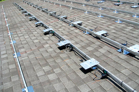
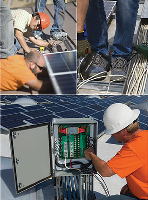
Figure 1. Large micro-inverter cable system prior to PV module mounting.
Types of PV Systems
A discussion of the various types of PV systems may help in deciding which wiring methods are most applicable for the installation. Once the wiring method is decided upon, the support methods become clear as they will be in accordance with the requirements set forth in the wiring method article unless modified in Article 690.
A system constructed of ac modules. These systems are defined in Section 690.2 and, to paraphrase, consist of “complete” units inclusive of the dc wiring and the inverter. In accordance with the listing requirements, these systems must be assembled by the manufacturer and, therefore, the only field wiring is the ac inverter output wiring. This is done in multiple ways but in all cases some length of cable assembly will have to leave each ac module. The types of cable assemblies and their attachment methods will be covered later.
A system constructed of a combination of dc wiring and micro-inverters with ac inverter output conductors. On these systems, the short lengths of cable used for the PV output circuit from the PV module to the micro-inverter must be supported. These single-conductor cables will be either listed PV wire or type USE-2 and are discussed in detail later in this article. In addition, the inverter output circuit will be treated in the same manner as the ac module circuits described in #1 above.
A system constructed with dc PV modules, PV source circuits and PV output circuits that terminate either in a combiner or an inverter. Where PV source circuit conductors are single-conductor cables, they must be either listed PV wire or type USE-2. These conductors and their protection tend to create the greatest degree of confusion and discussion between installers and inspectors. In addition to the specific wiring methods described in 690.31, any wiring method in the NEC, used in accordance with relevant Code restrictions, may be used for field wiring of PV equipment.
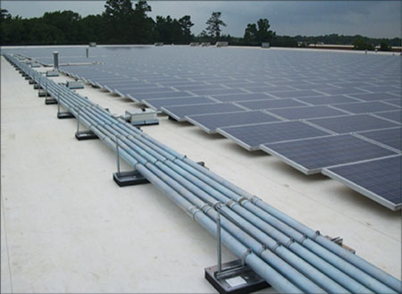
Figure 2. PV output circuits in EMT on commercial roof
PV Cable and USE-2
In Article 690, Solar Photovoltaic Systems, single conductor cable USE-2 and PV wire are permitted to be installed in exposed locations within the array [NEC 690.31(C)(1)]. The conductors connected directly to dc PV modules are either PV cable (marked as PV cable or PV wire) or USE-2. PV cable is similar to USE-2 but has additional insulation requirements for ultra-violet (UV) ratings and durability. PV cable is tested and listed in accordance with UL 4703, Photovoltaic Wire, which is a standard based on European standards for double-insulated cables used in European Class II wiring systems. This U.S. standard was developed in response to the 2005 NEC introduction of specific requirements for ungrounded PV systems in 690.35. At the time that the 2005 NEC was published, there was no relevant standard for double-insulated exposed cables in the United States. The 2005 NEC referred to the use of non-metallic multiconductor cable since the UL standard had yet to be established for PV wire. The 2005 NEC Handbook made reference to the development of the PV wire standard and encouraged AHJs to accept this wiring method as it became available. The 2008 NEC specifically referenced PV wire in 690.35(D)(3). Now PV cable is the standard of the industry for PV module wiring for ungrounded and grounded arrays (see figure 3).
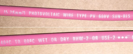
Figure 3. Markings on Listed PV Wire (also listed RHW-2 and USE-2)
What the NEC does not specifically address is the support of PV cable. Given the fact that PV cable is essentially an improved version of USE-2, it logically follows that the support methods required for USE-2 are sufficient for PV cable. A brief review of the Article 338, Service-Entrance Cable: Types SE and USE, is helpful for support requirements of type USE-2 cable. The installation methods for the exterior exposed SE cable is stated in NEC 338.10(B)(4) by referencing 334.30. Article 334, Nonmetallic-Sheathed Cable: Types NM, NMC, and NMS (NM is often referred to by the trade name Romex), states in 334.30:
“…cable shall be supported and secured by staples, cable ties, straps, hangers, or similar fittings designed and installed so as not to damage the cable, at intervals not exceeding 1.4 m (4½ ft) and within 300 mm (12 in.) of every outlet box, junction box, cabinet, or fitting. Flat cables shall not be stapled on edge.
“Sections of cable protected from physical damage by raceway shall not be required to be secured within the raceway.”
The provision for securement within 12 inches of a box is very well understood for NM cable in residential construction. The analogue in a PV array could be compared to the entry into a conduit system going underground or to a combiner box. These are subjective evaluation criteria and require the AHJ to provide their approval of the support methods. Figure 4 shows an example of the use of EMT to support and protect USE-2 cable.
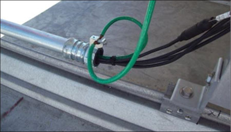
Figure 4. Exposed USE-2 cable protected and supported using EMT.
The issue here is that Section 338.10 addresses the proper support of type SE cable assemblies and not single conductor installations as would be the norm for PV installations. In fact, Section 338.12(B) specifically prohibits the use of type USE cable above ground except in short sections where it leaves the ground to terminate in equipment. Chapter 6, of course, can amend this and does so when these conductors are installed within a PV array or in raceways leaving the array. This lack of clarity in the NEC creates issues for AHJs and can cause a lack of uniformity in enforcement. A good commonsense approach to this problem is to use the referenced support requirements for type NM cable. The need for this clarification is understood and is being addressed in the 2017 NEC cycle. The basic requirements are very similar to single conductor knob-and-tube wiring that requires support within 6″ of terminations and every 4 ½ feet thereafter. This could also be considered as a reference for the support of single conductors.
Recommendations for Exposed Cable Support Methods
Article 334 mentions several support methods for exposed cables including staples, cable ties, straps, hangers, or similar fittings. This is a broad range of methods that need to be applied in context with the rest of the NEC. A common thread in the installation of electrical systems is that the work be done in a neat and workmanlike manner [NEC 110.12] and that conductors are not exposed to physical damage [NEC 300.4]. These two important concepts are at times overlooked in PV systems when installing exposed cable wiring methods.
Physical damage is not specifically defined in the NEC. However, it is understood as being self-defined. Preventing physical damage to electrical equipment in a parking garage may mean installing bollards or cages to keep cars from running into it [NEC 100 Enclosure, NEC 110.27(B), NEC 110.31(D)]. For conductors, it is also highly location-specific, and physical damage would mean obvious items that could damage the insulation on a conductor. This would include chafing on sharp edges, car traffic, and vandalism depending on the installation.
The NEC considers conductors and equipment above 8.5′ to be sufficient to be guarded against accidental contact [110.27(A)]. The 8.5′ measurement is new in the 2014 NEC for circuits above 300 volts up to 600 volts. By placing cables or equipment above 8.5′ (8′ for 300 volts and below), it may be possible to prevent damage due to accidental contact in a public area. These requirements in 110.27 are for shock protection, not for physical protection, so appropriate measures must still be taken to prevent physical damage where necessary. Figure 5 shows a clear violation of requirements for support and prevention of physical damage. In larger PV systems, a perimeter fencing and security system that keeps unqualified people out of the facility is sufficient to prevent accidental contact. However, since vehicles often need to be used within a large PV array, care should be taken in the design to prevent damage from vehicular traffic. This would include following rules for overhead conductors should vehicles be required to travel under cable management systems.
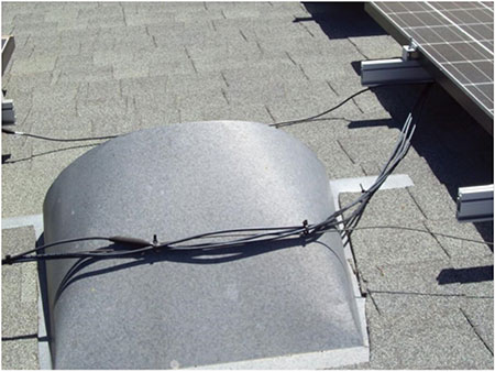
Figure 5. Insufficiently protected and supported USE-2 cable on a roof exposed to physical damage
Using Staples, Cable Ties, Straps, or Hangers for Cable Support
The NEC is not explicit about the size of conductors and the width of staples or other supports for cable support. NM cable staples may be listed specifically for the size and number of cables that it can secure and support. The authors are unaware of any similar requirement for cable ties. Some may argue that cable ties are not recommended since ANSI/NECA 1-2010, Standard Practice of Good Workmanship in Electrical is referenced in 110.12 as an example of accepted electrical industry practice. However, cable ties are commonly used within PV mounting systems and are allowed as a means of support provided they are adequate for the location including exposure to sunlight where necessary.
Cable Management Recommendations in ANSI/NECA 1-2010
Since the NEC references NECA 1, it is helpful to review that installation standard for any information that may be relevant to industry standard practice in this area. Again, it is important to reiterate that industry practice alone may not be directly enforceable, but it does provide guidance beyond the general requirements of the NEC. Chapter nine of this standard in entitled “Wire and Cable” and contains relevant information for exposed cable support. In the opening clauses in chapter nine there are several simple and clear statements regarding cable management:
“ c) Wire and cables shall be installed so as not to damage the insulation or cable sheath.”
- h) Cables that are installed exposed shall be run parallel and perpendicular to the surface of the building or exposed structural members and follow the surface contours as much as practical.
- i) Running boards shall be used where necessary to provide sufficient support and a neat installation. Care shall be taken to provide sufficient mechanical protection for exposed cables.
- j) All wires and cables, whether exposed, concealed or in raceways, shall be sufficiently supported using devices intended for the purpose.”
Item “c)” above is self-explanatory. Cable damage is unacceptable because of the obvious hazards of energized conductors [110.12]. Items “h)” and “i)” correspond directly with 334.15(A) and (B) and address the neatness of an installation and the importance of mechanical support of exposed cables. Lastly, item “j)” focuses on the intended purpose of supporting devices. An installer may argue that a piece of coat hanger or bailing wire could support a cable, but these devices are not intended for the use. A similar issue could be made of an electrical support item not used in its intended use. For instance, a one-hole conduit strap designed to support a 1″ EMT conduit could support an exterior cable. However, that device has sharp edges intended to help hold the conduit that can cause cable damage. The one-hole conduit strap device should not be used as a cable hanger since it is not intended for that use and can damage the cable insulation violating 110.12.
Lastly, there is a specific directive in the ANSI/NECA 1-2010 standard related to securement and support with cable ties.
“q) When using cable ties, do not over tighten, to ensure the cable tie does not cut the conductor’s outer jacket. Cable ties shall not be used to support raceways or cables.”
It is the recommendation of this best practices installation standard that cable ties not be used to support cables. It is common to see cable ties used in PV installation as the sole method of support. The NEC allows cable ties to be used for cable support, but this industry standard recommends against it. This clause also warns against the common mistake of overtightening cable ties to the point where they could damage the cable jacket. In summary, the requirements in the ANSI/NECA 1-2010 installation standard are commonsense items that state that exposed cables should be supported and secured in such a way that the cables are undamaged, neat, and supported and secured by devices intended for cable support.
The Specific Application of Cable Tray and PV Wire in Article 690
A new section of the 2014 NEC in Article 690.31(C)(2) for cable tray also illuminates the intent of cable management in a PV array (see figure 6).
“(2) Cable Tray. PV source circuits and PV output circuits using single-conductor cable listed and labeled as photovoltaic (PV) wire of all sizes, with or without a cable tray marking/rating, shall be permitted in cable trays installed in outdoor locations, provided that the cables are supported at intervals not to exceed 300 mm (12 in.) and secured at intervals not to exceed 1.4 m (4.5 ft).”
This new section mirrors the requirements of Article 334 in that it allows for securement intervals of 1.4 m (4.5 ft) just as required in 334.30(1). Article 392 of the NEC, which covers cable tray installation, does not require additional securement of cables for horizontal installations other than those required by the wiring method [NEC 392.30]. This means that Article 392 would only require securement at 4.5 foot intervals for USE-2, which is consistent with NEC 334.30. This is why Article 690.31(C)(2) requires securement at intervals no larger than 4.5 feet for USE-2 and PV Wire. The support requirements for cable tray are more stringent in 690.31(C)(2) than 334.30. One reason for the more stringent requirements is that PV wire as small as 12 AWG single conductor cable is common in PV systems. In a cable tray that has ladder-type rungs for cable support, the maximum allowable distance between rungs is 12 inches according to 690.31(C)(2).
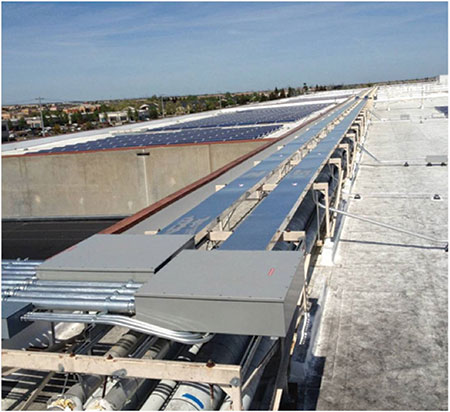
Figure 6. PV output circuits in covered cable tray on commercial roof
Installation Recommendations for Cable Staples, Straps, and Hangers in PV Systems
Following both support and securement requirements outlined in 690.31(C)(2) for cable trays may be a commonsense approach to the use of other support and securement methods. Applying the basic approach in 690.31(C)(2), means that cable staples, straps, and hangers should be placed at 12″ intervals, and the cables secured to straps or hangers using cable ties at every fifth hanger (4 feet between securements). This basic approach is consistent with the requirement in Article 690.31(C)(2) for cable tray and would allow any size conductor to be used in the support method [see figure 8].
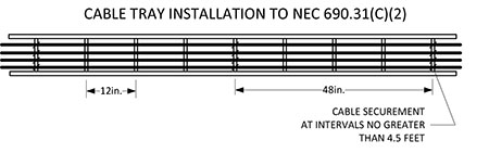
Figure 7. Cable tray installation in accordance with Article 690
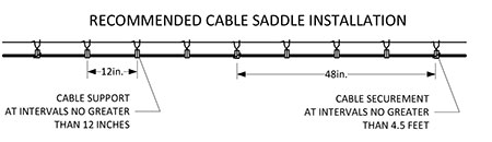
Figure 8. Cable hanger installation recommendation
Figure 9 shows an installation that may technically be compliant with the NEC, but could be viewed by some as violating 110.12 or 300.4. Given the mechanical strength of larger conductors (1/0 AWG and larger), it would be possible to use a greater distance between staples, straps, or hangers for support while the securement distance should not increase past 4.5 feet. For example, if a group of four 4/0 AWG aluminum USE-2 cables were run in a cable hanger system, a distance of 18″ between hangers would be sufficient for support while every fourth hanger would have cable tie securement (4.5 feet between securements). The reason 18″ was chosen as a maximum distance between hangers is that it is consistent with commonly available cable tray rung spacing. The 12″ support distance should be used for cable sizes less than size 1/0 AWG.
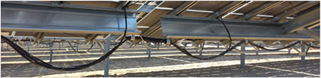
Figure 9. 10 AWG USE-2 cable with 4.5′ distance between supports
Cable Support Methods in Large Ground-Mounted PV Systems
Since many ground-mounted PV arrays have tracking systems that use ac power to drive the tracker systems, an installer may want to install the ac conductors in the same cable support system with the dc conductors. In the 2011 and prior versions of the NEC, it would be acceptable to have the cables in the same hanger as long as the conductors are bundled separately [2011 NEC 690.4(B) and NEC 690.4(B)(4)]. However, there is a significant change in the 2014 NEC that disallows dc and ac conductors, even when part of the same system to be installed in the same raceway or enclosure unless a partition separates them. Figure 10 shows an example using a messenger wire with a cable hanger for the dc and ac cables. This hanger provides for three different types of exposed cables. The same coated wire is used to create two main cable sections for the dc and ac conductors, but a third section at the top of the ring is provided to install a communications cable.
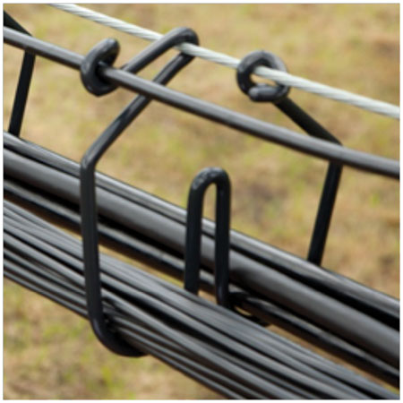
Figure 10. Cable ring with three cable sections. Photo courtesy of CAB Products.
This is key because the required communications cable may not be of the same voltage rating as either the dc or ac cables. Since the communications cable is kept separate from the dc and ac cables, the voltage rating of the communications cable need only be sufficient to withstand the voltage of the communication circuits. This third section can have a significant value for the support of exposed cables since the Code would require that the communications cable have the same rating as any conductors it contacts. Finding communications cables with ratings above 150 volts can be difficult not to mention expensive. Both dc and ac circuits used in most large ground-mounted systems are well above 150 volts.
Grounding and Bonding of Cable Supports
The electrical industry, including code-enforcement personnel, is heavily focused on grounding and bonding of metallic parts. The primary concern is contact of exposed metal parts with conductors having damaged insulation—thus energizing the metal parts. Consider a metallic cable hanger like the one shown in figure 11. These types of cable supports would fall under the definition of “fitting” in Article 100 of the NEC.
“Fitting. An accessory such as a locknut, bushing, or other part of a wiring system that is intended primarily to perform a mechanical rather than an electrical function.”
Some AHJs may believe that exposed metal straps or hangers should be evaluated for bonding. This is not well substantiated in the NEC, nor is there a UL standard for evaluating such equipment. As an example, metallic cable staples for NM cable are not required to be bonded. The NEC simply states in Article 334.30 that, “Nonmetallic-sheathed cable shall be supported and secured by staples, cable ties, straps, hangers, or similar fittings designed and installed so as not to damage the cable….” Clearly, damage to the cable is the issue. With this understanding, a cable hanger or similar fitting should be permitted to be installed without a listing for bonding and grounding, provided they do not damage the cable. In the example shown in figure 11, the hangers are actually in solid contact with a grounded steel messenger wire. It could be argued that even if the cable insulation were ever to be damaged, the cable support would stay at or near ground potential.
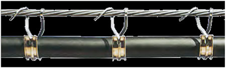
Figure 11. Cable hanger installation. Photo courtesy of CAB Products.
Ultimately, the AHJ must approve any equipment used in a PV installation under their purview. If an AHJ does not accept cable hangers as being designed to prevent damage to the cable, a simple way to resolve the need for bonding this product is to install straps or hangers with a non-conductive coating so that the metal of the supports never come in contact with the cable. An example of a cable hanger with this type of coating was shown in figure 10.
Ampacity of Conductors Bundled in a Cable Support
Another important concern of the AHJ is the ampacity of the conductors. Clearly, a USE-2 installation such as the one shown in figure 11 should be considered as a free air installation and subject to the free air ampacity table, Table 310.15(B)(17), for ampacity values. However, as cables are bundled together, as in figure 10, the inner conductors are not in free air and their ampacity is similar to conductors in a raceway. The NEC is specific on this issue for cable trays in Article 392. Uncovered cable trays with multiconductor cables [392.80(A)(1)] require the use of Table 310.15(B)(16) as a starting point. When a cable has more than three conductors in a bundle, it requires using the adjustment factors for conduit fill in Table 310.15(B)(3)(a).
While the NEC is not specific for bundling conductors other than in cable trays, to be conservative, a cable bundle of three cables should be subject to the ampacity limitations of Table 310.15(B)(16) which is used for up to three conductors in a raceway. Since outdoor ambient design temperatures are generally above 30°C for most of the United States, an additional correction factor for temperature should be applied according to Table 310.15(B)(2)(a). For more than three cables in a bundle, Table 310.15(B)(3)(a) should adjust the ampacity further.
In summary, it appears that it is appropriate to use the free air table [Table 310.15(B)(17)] only for unbundled single conductor cable. This may be slightly conservative, but it is difficult to justify another position from the language of the NEC. In the future, with supporting research on specific applications, it may be possible to use Table 310.15(B)(17) rather than 310.15(B)(16) for bundled conductors.
Multiconductor Cables in PV Systems
The 2014 NEC has a new section providing details on the installation of multiconductor cable in PV system inverter output circuits in 690.31(D).
“(D) Multiconductor Cable. Multiconductor cable Type TC-ER or Type USE-2 shall be permitted in outdoor locations in PV inverter output circuits where used with utility-interactive inverters mounted in locations that are not readily accessible. The cable shall be secured at intervals not exceeding 1.8 m (6 ft). Equipment grounding for the utilization equipment shall be provided by an equipment grounding conductor within the cable.”
Type TC-ER is currently being used in most listed micro-inverter and ac PV module systems for the ac output circuit exposed cable. Some AHJs have disallowed the installation of this wiring method because the use of the cable is prohibited for other than the installation methods that are delineated under the methods permitted in section 336.10 of Article 336, Power and Control Tray Cable: Type TC. This new provision is consistent with the requirements of 336.10(7) except that it expands the use of TC-ER beyond the specified limitations of specific uses within industrial establishments. To be consistent with the requirements of 336.10(7), it also allows for a slightly further securement interval than that required for single conductor PV cable or USE-2. It is understood that some PV system manufacturers are delving into further testing of TC-ER cables so that it is clear that product standards properly address installation methods allowed in the NEC.
Keeping in mind the authors’ recommendations for cable support at intervals of 18 inches for larger cables, a multiconductor TC-ER or USE-2 cable may be mechanically similar to a 1/0 single conductor cable. These authors recommend that when these conductors are installed in PV inverter output circuits, they be supported at 18 inch intervals and secured at a minimum of 6-foot intervals (see figure 12).
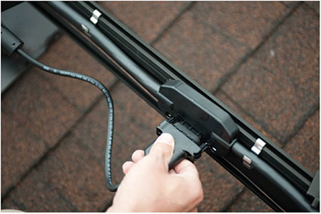
Figure 12. Factor cable assembly with proper support. Photo courtesy of Enphase Energy.
Conclusion
Since the NEC is somewhat subjective on the part of exposed cable management procedures, it is ultimately the job of the AHJ to rule on the issues of neat and workmanlike installation techniques and what comprises exposure to physical damage. NECA 1 provides some additional insight to guide the understanding of industry practice related to physical damage and workmanship. Ultimately, exposed cables in PV systems need to be designed and installed in such a way that the wiring method stays safely intact for the life of the PV system which may exceed 50 years. While this may be a tall order, it is no less than we expect of our service drop cables. It is clear that our cable materials are capable of lasting provided we use good installation practices. Hopefully, the NEC will evolve in this area by providing additional direction to assist contractors and AHJs install and approve long-lasting, well-supported exposed cable wiring systems. This does not mean that the support methods should not be checked periodically by the PV system owner, especially when they are installed in harsh environments.