The fundamental purpose of overcurrent protection is to protect conductors and equipment against the effects of excessive temperature on conductors and conductor insulation from overcurrent.
Some of the issues we might not be fully familiar with are these:
- What devices are suitable for branch and feeder overcurrent protection?
- Matching device rating to system voltage
- Application at 80 percent versus 100 percent of current rating
- The difference between an interrupting rating and a short-circuit current rating
Overcurrent Protection Basics
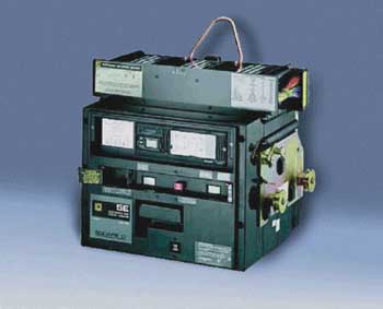
Photo 1
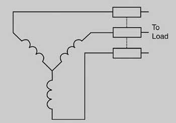
Figure 1. The ungrounded system of figure 1 is an example of a straight rated system.
Understanding the basics of an overcurrent condition and the purpose for overcurrent protection will establish the foundation for our discussion. Article 100 of the National Electrical Code (NEC) defines overcurrent as:
“”Any current in excess of the rated current of equipment or the ampacity of a conductor. It may result from overload, short circuit, or ground fault.
FPN: A current in excess of rating may be accommodated by certain equipment and conductors for a given set of conditions. Therefore the rules for overcurrent protection are specific for particular situations.””
The purpose of overcurrent protection is found in the FPN of NEC 240.1, which states:
“Overcurrent protection for conductors and equipment is provided to open the circuit if the current reaches a value that will cause an excessive or dangerous temperature in conductors or conductor insulation. See also 110.9 for requirements for interrupting ratings and 110.10 for requirements for protection against fault currents.”
Two categories of devices are acknowledged by the NEC as overcurrent protective devices (OCPDs): circuit breakers and fuses. These devices have means to detect values of overcurrent and to “interrupt” the current according to a time-current characteristic, when overcurrent is detected. NEC 110-9 and 110-10 clarify that the devices must have the interrupting ratings that will allow them to interrupt the fault current at nominal circuit voltage that may be available at the line terminals of the equipment containing the circuit breaker or fuses.
The basic points of overcurrent protection are:
- OCPDs are fuses or circuit breakers.
- OCPDs protect against excessive temperature of conductors and their insulation.
- OCPDs protect in event of overload, short circuit and ground fault.
- OCPDs must have an interrupting rating sufficient for the prospective fault current at nominal voltage.
Voltage Rating
A proper voltage rating of the OCPD is essential for interrupting the circuit. In order to understand voltage ratings, it is important to understand “straight” ratings and “slash” ratings.
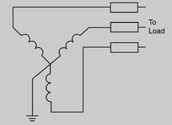
Figure 2. The solidly grounded system of figure 2 is an example of a slash rated system
Systems and voltages applied in the USA are detailed in Chapter 3 of the IEEE Red Book1. A straight rating expressed as 240 or 480 V would imply a system operating with no line-to-line voltage exceeding the rating number and with no leg broken for a grounding connection. The ungrounded system of figure 1 is an example of a straight rated system. In a slash rating expressed as 120/240 V or 480Y/277V, the higher number is the greatest line-to-line voltage and the lower number is the greatest voltage of any conductor to ground. The solidly grounded system of figure 2 is an example of a slash rated system.
Fuse Voltage Ratings
Fuses have a variety of voltage ratings including 125, 250, 300 and 600 V ac. Their single-pole nature generally makes application of the voltage rating seem obvious. However, 3-phase applications may not be so obvious.
NEC 240.60(A) provides a requirement for fuses rated 300 V. It states: “Cartridge fuses and fuseholders of the 300-volt type shall be permitted to be used in the following circuits:
1. Circuits not exceeding 300 volts between conductors
2. Single-phase line-to-neutral circuits supplied from a 3-phase, 4-wire, solidly grounded neutral source where the line-to-neutral voltage does not exceed 300 volts.
This requirement excludes the use of 300-V fuses in 3-phase, 4-wire circuits rated 480Y/277 V. Since the voltage from linetoneutral is 277 V in those circuits, it might seem appropriate to use 300-V fuses. However, the interruption is a 3-phase interruption and the fuses are opening independently. As one fuse begins to arc, it places a high resistance in the phase in which it is installed and causes the current and voltage to become very unbalanced. Under these conditions, the voltage across a pole may considerably exceed 300 V and interruption may not be successful. A fuse rated at least 480 V is needed for this application, which is normally a 600-V fuse.
NEC 240.61 clarifies that fuses may be used for voltages below their ratings. A 600-V fuse may be used in a 480-V system.
Circuit Breaker Voltage Ratings
NEC 240.85 clarifies that a straight rated circuit breaker may be applied where the “nominal voltage between any two conductors does not exceed the circuit breaker’s voltage rating.” For example, a circuit breaker rated 480 V is suitable for use on systems of either figure 1 or 2 where line-to-line voltage is no more than 480 V.
That same NEC section also clarifies the application of slash rated circuit breakers.
“A circuit breaker with a slash rating, such as 120/240 V or 480Y/277 V, shall be permitted to be applied in a solidly grounded circuit where the nominal voltage of any conductor to ground does not exceed the lower of the two values of the circuit breaker’s voltage rating and the nominal voltage between any two conductors does not exceed the higher value of the circuit breaker’s voltage rating.”
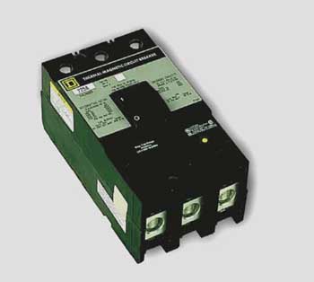
Photo 2
These slash ratings would not be suitable for use on a system that is ungrounded, figure 1, or grounded through an impedance, figure 3. They also would not be suitable for use on a system in which the voltage to ground is greater than the lower number such as would be the case in a corner-grounded delta system, figure 4.
However, a circuit breaker rated 480Y/277V would be suitable for use on a 240-V ungrounded or impedance grounded system since the line-to-line voltage is lower than the lower number in the slash rating.
NEC 240.85 FPN
A new fine print note was added to NEC 240.85 indicating that, for other than solidly grounded WYE systems, and especially corner-grounded delta systems, application of circuit breakers will consider the single-pole interrupting capability. What it refers to is that individual-pole testing of molded-case circuit breakers (MCCBs) may be inadequate for some corner-grounded delta systems. All MCCBs are tested for individual-pole interruptions in accordance with the industry developed standard UL 489, the Standard for Safety for Molded-Case Circuit Breakers, Molded-Case Switches and Circuit Breaker Enclosures. However, the individual-pole test is at a lower value than the interrupting rating for most circuit breakers. These lower testing values are appropriate for a majority of electrical systems. The new FPN is advising that corner-grounded systems have the unique condition that a line-to-ground fault is at full line voltage and could be up to 87 percent of available 3-phase fault current. The authors recommend that MCCBs used on corner-grounded systems be rated specifically for that application.
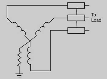
Figure 3. Impedance grounded WYE system
To be comprehensive on the subject, we should mention a possible condition for impedance grounded or ungrounded systems. When multiple faults to ground occur simultaneously on different phases, one on the supply side and one on the load side of a MCCB, they could theoretically place a fault across a single pole of the circuit breaker at near line voltage. However, the probability of having that fault is very low and the probability that it will be above the fault level for which the MCCB is tested is even lower. MCCBs have provided good protection in these systems for decades. Rapid removal of the first fault is a key to safe operation in any case.
Current Rating
OCPDs are intended to protect against excessive temperatures in conductors or their insulation. It is essential to match the current rating of the OCPD to the conductor size. The current flowing through the conductor, which has a resistance, generates heat; reducing the conductor size from those found in the appropriate column in NEC Table 310-16 will place the conductor at risk of thermal damage.
Branch and Feeder Circuits
For branch circuits, NEC 210.19 states the rules for sizing conductors. The general rule is that conductors are sized to have an ampacity of not less than the noncontinuous load plus 125 percent of the continuous load. The corresponding rule for overcurrent protection is given in NEC 210.20(A). It states that the OCPD rating is to be not less than the noncontinuous load plus 125 percent of the continuous load. According to the definition in Article 100, continuous load means that it continues for 3 hours or more. Similar rules for feeders appear in NEC 215.2 and 215.3. Two points are clear:
- Ampacity of the conductors is matched to OCPD rating by the same rule.
- OCPDs are sized for 125 percent of continuous current, which means that they are expected to carry continuously 80 percent of rated current.
100 Percent Rated Devices
NEC 210.19, 210.20, 215.2, 215.3 and 230.42 permit conductors and overcurrent protection to be rated for 100 percent rather than 125 percent of continuous current “where the assembly, including the overcurrent devices protecting the [circuit] is listed for operation at 100 percent of its rating.” An important factor is that the assembly, meaning the switchboard, panelboard or similar equipment, is listed for operation at 100 percent of its rating as well as the OCPD. The additional current flowing will cause additional heat. If the assembly has not been listed for this application, temperatures may easily become excessive for the conductors and insulation.
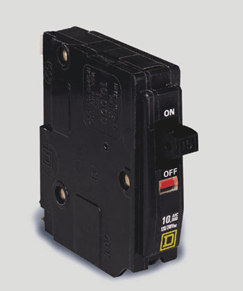
Photo 3
Because higher temperatures are frequently experienced with this rating, the listing may require the use of conductors rated 90°C but sized according to the 75°C ampacity rules. The circuit breaker will be so marked if 90° conductors (insulation rating) are required just as it will be specifically marked for use at 100 percent of its rating.
How are 100 percent rated MCCBs applied compared to standard MCCBs?
For a branch, calculate the load as indicated in NEC Article 210. Select the conductor size as indicated in NEC 210.19. Then determine the overcurrent protection in accordance with NEC 210.20.
Imagine a circuit with a 300-A noncontinuous load plus a 50-A continuous load. Conductors must be sized for 363 A by 210.19(A) if a standard overcurrent protective device is to be used. Two 3/0 AWG copper conductors are selected. In accordance with NEC 210.20, a 400-A MCCB is selected.
If a 100 percent rated MCCB is to be used, conductors are sized for 350 A and two 2/0 AWG copper conductors are selected. In accordance with 210-20, a 350 A, 100 percent rated MCCB is selected. The 100 percent MCCB may be marked to require the 2/0 AWG conductors to be rated 90°C (90°C rated insulation and sized by the 75°C column in Table 310.16)
The 100 percent rating does not apply when a MCCB is used for motor circuit protection under NEC Article 430.
Conductors
There is no provision for the use of construction wire or cable with a temperature rating of 90°C using 90°C ampacity for distribution or control equipment in which OCPDs are used. This condition applies to the circuit breakers and fuseholders as well. This question arises frequently. Some wire connectors are marked as suitable for 90°C conductors, but that does not mean that the equipment on which they are used is suitable for 90°C conductors at 90°C ampacity.
The general rule is stated in NEC 110.14(C). For equipment listed to UL standards, that information is repeated in Underwriters Laboratories General Information for Electrical Equipment under Guide Category AALZ. Unless the device is marked to indicate otherwise, the wiring space and current-carrying capacity are based on the use of 60°C wire where wire size Nos. 14-1 AWG are used and 75°C wire where wire size Nos. 1/0 AWG and larger are used. If the equipment, normally intended for connection by wire sizes within the range 14-1 AWG, is marked “75C” or “60/75C,” it is intended that 75°C insulated wire may be used at full 75°C ampacity. A 75°C or 90°C temperature marking on a terminal (e.g., AL7, CU7AL, AL7CU or AL9, CU9AL, AL9CU) does not in itself indicate that 75°C or 90°C insulated wire can be used unless the equipment in which the terminals are installed is marked for 75°C or 90°C at that ampacity.
Interrupting Rating
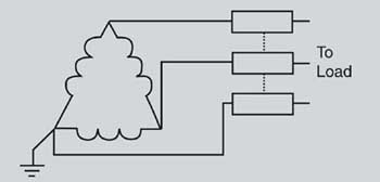
Figure 4. Corner-grounded delta system
Every fuse and circuit breaker is assigned an interrupting rating. It consists of a maximum current and the voltage at which the device is rated to interrupt the circuit. Some devices will have multiple interrupting ratings, such as 14,000 amperes at 600 volts and 25,000 amperes at 480 volts. These interrupting ratings will be marked unless they are the lowest rating permitted, which is 10,000 amperes for cartridge fuses or 5000 amperes for circuit breakers at the voltage rating of the device.
The interrupting rating is essential in order to know that the device is capable of protecting conductors and itself in the event of a short circuit or ground fault. NEC 110-10 also requires that the OCPD must “clear a fault…without extensive damage to the electrical components of the circuit.” This does not mean that all components of the circuit should be suitable for continued service. However, it does mean that the circuit could be re-energized after the short circuit is removed without posing an immediate hazard. Before being placed back in service following a short circuit, all conductors and components in the path of the short circuit should be examined for potential damage. Repairs and replacements must be done before the circuit is used again.
OCPDs listed to industry standards are suitable for use where the potential fault current of the interrupting rating is present at the line terminals of the equipment as stated in NEC 110.10. The term interrupting rating implies that they are suitable to interrupt the overcurrent condition and clear the circuit.
Equipment in the distribution and control systems will have a short circuit current rating (SCCR). The distribution and control equipment will identify the OCPDs and short-circuit current rating associated with each device. The final rating of the installed equipment is generally determined by the lowest rated OCPD or combination of device (Series Combination) used with the equipment.
Summary
Overcurrent protection depends on correctly matching the voltage rating of the OCPD to that of the system, matching the current rating to the calculated load and the conductors and matching the interrupting rating to the available fault current at system voltage. Marked ratings of listed equipment will support safe application as long as the system is understood.
1 IEEE Standard 141-1993, Recommended Practice for Electric Power Distribution for Industrial Plants (Red Book), Institute of Electrical and Electronics Engineers, New York, NY