Overcurrent protection is a subject on which we could write volumes; however, our objective here is to cover the basics in order to provide the information needed for the combination inspector. This is actually a fun portion of training, as we usually take apart devices and explore how they operate. Check out the included photos that illustrate some of the details that we usually look at in training classes, and don’t be hesitant about disassembling equipment (that you don’t plan to install later!) to see what is inside.
To make sure we understand our topic, we need to start with the scope of this article. It provides the general requirements for overcurrent protection and overcurrent protective devices not more than 600 volts, nominal. There are two parts to Article 240 that we will not address: Part VIII dealing with supervised industrial installations and Part IX dealing with over 600 volts. Combination inspectors are generally not involved with these installations, so we will leave those topics to articles and books specifically concerned with those subjects.
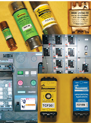
Photo 1. Overcurrent protection comes in many types, sizes and shapes
As with most NEC articles, we need to start with some unique definitions. Article 240 has only three definitions, and they are located in 240.2. First we have a definition of current-limiting overcurrent protective device, which is a device that when interrupting currents in its current-limiting range will reduce the current flowing downstream to a level much less than if there were just a solid conductor having comparable impedance. Current-limiting devices are very instrumental in reducing incident energy (arc flash, arc blast) in our electrical systems, making them safer for personnel and providing protection of equipment.
The second definition deals with a term that is also used in other parts of the code. Quite often we have a question as to what exactly is an “industrial installation”? In 240.2, we have a definition of supervised industrial installation with a list of conditions which must be met to fall under this definition. Note that this definition is specifically limited to use in Part VIII of Article 240; this means that these limitations do not apply to any other code provision where supervised industrial installation (or similar term) is used. You can’t use this definition when applying 392.10(B), for example, which allows certain cable tray wiring methods in industrial establishments. Since we are not covering Part VIII in depth, I simply point this out so that you know that this definition is very limited in application.
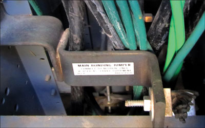
Photo 2. Here is a very good example of a neutral main bonding jumper that was never properly connected after the completion of the ground fault testing. This caused several problems within this facility, including voltage fluctuations and equipment failures.
The last definition is that of a tap conductor as used in this article. This definition is needed as we have various tap rules within Article 240 with very specific rules. Simply put, a tap conductor is a conductor other than a service conductor that has overcurrent protection ahead of it which is oversized compared to the normal requirements found in Article 240.
Basic minimum overcurrent protection
So, let’s get down to the most basic of rules for overcurrent protection. The go-to article here is 240.4. Other than flexible cords, flexible cables and fixture wire, we refer to the ampacities of the conductors as specified in Article 310.15, unless covered in specific applications as described in 240.4(A) through (G). In these subparagraphs, we cover basic minimum overcurrent protection device sizing according to conductor sizes and properties. These are very basic rules that will at times get overlooked when using ampacity tables, but you absolutely need to try to commit these to memory. Also, many code test questions will ask about sizing a certain type and size conductor, and you’ll get sidetracked into doing a calculation and don’t want to forget that you have limitations in 240.4. Please review these and remember some basic ones such as 14 AWG copper must have 15 amp protection, 12 AWG copper is limited to 20 amps and 10 AWG copper at 30 amps, just to name a few.
There are two very important rules in 240.4 that we have to examine more closely, as they deal with protection for 800 amps and lower and then over 800 amps. These general rules state that if you are sizing protection for 800 amps or lower, you are allowed to round up to the next largest device, as long as you don’t violate the specific conductors mentioned in 240.4(D). If you have a system over 800 amps, then the ampacity of the conductors has to equal or exceed the rating of the overcurrent device.
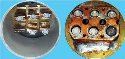
Photo 3. This is a photo showing the interior of a 600-amp fuse after the sand filler has been removed. This fuse opened during an overload condition. You can see how five of the six alloy contact points melted and released; when the last one interrupted the flow of current, it arced and caused the burned sixth contact. Please note in the left photo you can see the short-circuit elements which are still intact; these are the webs which melt out during a high fault current condition.
The next question that usually comes up here is: When allowed to round up to the next size device, what is the next size? The next size according to what is available from the manufacturer? No, you round up to the next standard size device according to 240.6. Please notice that in 240.5 you will find the specific overcurrent sizes for flexible cord, cables and fixture wire; again, the rules are very specific and in part mention exact size overcurrent protection according to the wire size. Please review, but know that generally speaking, we don’t see these wire types that often in combination inspections.
Standard ampere ratings
Let’s go back to Standard Ampere Ratings in 240.6. This is one section of your code book you will need to reference almost as often as conductor ampacities, so please remember it. Here you find what the code considers “standard sizes” when references are made to sizing overcurrent devices. I always make a big point of making sure everyone uses the sizes listed in this article when working on code questions or test questions. Another note here, remember when we had the rule that you round up when working at 800 amps and below? Well, you will notice the size differences below 800 amps are much closer, so when we round up it’s not much of a shift; however, when you get over 800 amps you will notice there are not as many options and the sizes start to jump in pretty large increments. This helps to explain the reasoning behind this code requirement, since rounding up in such large steps could lead to a large disparity between conductor ampacity and overcurrent protection levels.
Also in 240.6 are two paragraphs, (B) and (C), which work together to address adjustable trip circuit breakers. If you have an adjustable breaker which has the adjustment exposed with ready access, then the rating of that breaker will be the maximum possible setting. However, if these controls have a restricted access feature meeting the requirements as set forth in (C), then the rating of this device will be at the set value. The one gray area here is that some of the breakers have a field-fitted rating plug. It was my opinion as an inspector that if this plug type device could not be removed without the removal of sealable covers or special tooling of some sort, we applied 240.6(B). One such case had a plug which could easily be removed using a pair of needle nose pliers, so we opted for the conservative approach and applied (C).

Photo 4. This photo shows the inside of a breaker. You can see some of the mechanical parts that are required for proper operation.
Fuses or circuit breakers in parallel
Questions appearing on some tests ask if it is permissible to use fuses and circuit breakers in parallel. This is addressed in 240.8. The correct answer is: only where they are a part of a factory assembly and listed as a unit. I have seen this from time to time, but never outside a factory listed unit.
Electrical system coordination
Continuing on, 240.12 starts us on the path for an interesting concept that often isn’t considered in design. The subject is electrical system coordination, and it simply states that to minimize hazard(s) to personnel and equipment where an orderly shutdown is required, a system of coordination based on two conditions shall be permitted. The first condition is coordinated short-circuit protection and the second is overload indication based a monitoring system or devices. Notice that this language says “shall be permitted.” This means that is allowed, but not required. This language is generally applied to situations where it is more hazardous to shut down the electrical source than it is to shut down the process. This is not the same as selective coordination, which is required for many emergency systems and will be covered when we finally get to Chapter 7.
Ground-fault protection of equipment
In 240.13 we find requirements for Ground-Fault Protection of Equipment. Let’s first consider the difference between ground-fault circuit interruption (GFCI) and ground-fault protection. The easiest way to explain this is that GFCI protection is for people and the threshold levels are extremely low (around 5 ma), whereas the protection of equipment is meant to minimize the damage to equipment in the event of a fault condition to ground. This applies to only a very specific power configuration and that is a solid wye-connected system, where the voltage to ground is more than 150 volts and the phase-to-phase voltage does not exceed 600 volts. Commonly this will be our 277/480 volts wye-connected three-phase systems that are 1000 amperes or more in size. Ground-fault protection offers a level of protection in the event of a ground fault at a much lower level of current than what the breaker is equipped to handle under normal operation. I’ll tell you a personal experience related to this. We had a bank in our jurisdiction where the service was rated at 1000 amps, 277/480 and so the inspector made a note that this installation would require ground-fault protection. The engineer stated it didn’t need it because he had specified an 800-amp main breaker. A little gray area I guess, but we decided to stick with the rating of the manufacturer’s label which stated the service equipment was 1000 amps. The end result was that the factory sent out new equipment labels and had a field inspection done by a listing agency to change the equipment to an 800-amp service officially.
Ground-fault protection needs a little deeper look, first to understand how it works and then to understand some of the complexities to look for as you are doing your inspections. First, these devices have a sensing ability to verify that the amount of current being called for is balanced and all accounted for between the other phases or the grounded conductor. In the event that we have current going to ground or not following the normal paths, then the ground-fault protection will open the device (this could be a breaker or a bolt switch equipped with the ground-fault protection). When these devices are sent out, they are set at factory minimums. If the levels are not adjusted at the time of installation, this minimum setting may cause nuisance tripping. The setting should be evaluated and specified by the engineer of record, and then set in the field to match the engineer’s design.
Once I got a service call for a large grocery store that had lost power. The main at this store had ground-fault protection, and the original contractor didn’t set up the device as requested by the engineer of record. So, it was still set at the minimum value. On the evening I got the call, the manager had asked a box boy to paint the hallway going upstairs to the break room, and the young man had saturated his roller to the point it caused some large drips to start running down the wall. The paint flowed into a 277-volt switch box and shorted out the switch. Well before the individual circuit breaker which fed the lighting circuit could interrupt the fault, the ground-fault device saw the fault to ground, did its job, and shut down the entire store. Because the device was not properly set by the installer, the entire facility lost power.
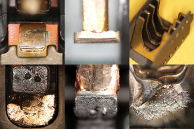
Photo 5. This collage of photos shows a before-and-after for breakers. The top row shows a breaker which has not been in operation. The left and middle photos show both sides of the contacts, and the right photo shows the arc chutes. The bottom row shows an example of the same parts of another breaker which has been subjected to a high fault current condition and had to open, causing damage to its components.
Total separation of grounds and neutrals
Now one of the critical items we must look at during inspection is the total separation of grounds and neutrals downstream of the ground-fault device. This must be done all the way throughout the system down to each branch-circuit device and the equipment connected to the system. At the main service we have to pay special attention to have the grounds connected only to the grounding bar, and neutrals connected only to the neutral bar. Now this is different from our normal method, say in a residential main panel, where we can just mix the grounds and neutrals as we see fit. In these larger systems, there is a neutral bonding jumper (which could be a conductor but is generally a piece of busing) that comes from the factory and is not connected to the ground bar. As an inspector, you have to verify that the grounds terminate on the ground bar and the neutrals, to the neutral bar. If these are not done properly, the system will have issues.
Locally we always required third party verification and testing of the ground-fault system before we would approve it to be energized. This was our insurance that the unit had the grounds and neutrals separated throughout the entire facility and that the system wasn’t left at factory minimums. Once the system has been checked, then the neutral bonding jumper is connected between the neutral and the ground bar. So after we got this report, we would make sure the bonding jumper link was connected between the neutral and ground bar and then allow the contractor to have the system energized. This was our solution for enforcement of ground-fault protection of equipment.
In the next issue we will pick up with Part II of Article 240, but this is a good time to cover a related issue. While teaching classes on the code, I always tried to take the mystery out of the electrical system as much as possible. So I am going to spend a little time explaining how overcurrent and short-circuit protection works. In class this always led to a lot of show and tell, taking apart devices and physically seeing their operation. I will try to explain this here and supplement it with some good photos.
Basics of circuit protection
We need to explore some of the basics of circuit protection. First we’ll start with the most common circuit breaker in the industry today, that being an inverse time circuit breaker. These come in all sizes and ratings, from 15 amps and up. They are rated by amperage, voltage and interrupting rating. The first two items we should already be familiar with; however, the last is often overlooked. The interrupting rating is the amount of fault current the device is able to safely handle without catastrophic failure. Insuring the available fault current is less than the rating of the device is one of the inspection items we need to look for. Breakers are mechanical equipment; similar to any other mechanical device, they require a lot of pieces to work together with the proper timing to do their job. A car is a good comparison, as it is a mechanical device that has many pieces that have to operate in a certain sequence for proper operation. Also similar to cars, the need for exercise and maintenance for breakers should be considered. Inside a breaker we have two distinct methods which cause it to open, one being an overload which is normally up to about 6 times the handle rating, and the other being the short-circuit portion which reacts to shorts causing a high level of fault current to flow. The overload is normally handled by a bi-metallic element which when exposed to excessive current starts to heat up and it then deflects to contact the trip bar and release the trip mechanism. Breakers handle short circuits with a magnetic sensor which reacts to high current flow and opens a breaker as fast as it can. Remember these are mechanical, and as such they take a certain amount of time to react and then to complete the operation of shutting down the circuit. The photos illustrate the number of components inside a breaker and also show a close up of the contacts, the arc shields which control and manage the arcing when operating in high-fault conditions, and a bi-metallic strip.
The other most common method of circuit protection is fuses, which in many circles is considered old style due to the fact they’ve been used to protect electrical systems practically since the beginning. However, they still have a distinct use in today’s systems and provide some very unique methods of protection due partially to their simpler operation. The most commonly used fuse for construction is a dual element time-delay fuse. These have two distinct portions within each fuse; the first portion is a thermally reactive element which handles an overload situation. This element uses a melting alloy which has been specifically created for each size fuse. When it is exposed to an overload condition it will melt out and release, allowing the fuse to open. The short-circuit section of a fuse consists of a web-style design which is designed to react to high-current flows and very rapidly melt out; as these melt and break away, the amount of metal mass left is diminished which limits the amount of current which can continue to pass through the fuse. Therefore, they are considered current-limiting by design. In order to control this arcing within the fuse, it is filled with sand. When the sand comes into contact with the extreme heat and arcing of the webs, it turns into glass to quench the arcing event and extinguish it.
I know the operation of a fuse sounds basic compared to a device full of mechanical components which have to work in unison, but that’s just how simple they are. Once a fuse opens, you replace them with a new fuse which restores the system back to its original level of protection. When a breaker has been subjected to fault current near its operating limit, it should be taken out of service and tested before using again. There are companies that test breakers to insure they operate in the proper time and current levels required and then re-certify them. If the breaker is not tested and re-certified, it may not protect the system during a future fault.
In the next issue we will continue with Article 240. Continue to review the code as these articles only cover the highlights you need to know.




Find Us on Socials