Part I, which appeared in the March/April issue, provided readers with information about basic operation and basic time-current characteristics of branch-circuit, low-voltage fuses and circuit breakers. This article covers three overcurrent protective device ratings, their application in design, and NEC compliance aspects of low-voltage branch-circuit fuses and circuit breakers. These overcurrent protective devices (OCPDs) are typically used in main service disconnects, feeders and branch circuits of residential, commercial, institutional, and industrial electrical systems. There are other OCPDs used in 600 V or less electrical distribution systems that this article does not directly address. However, many of these principles presented also apply to the other type devices. This article focuses on the basics and as you probably already know, the Code is comprehensive and complex. As a consequence, the information in this article cannot be assumed to be applicable for all types of applications and wiring situations.
Why Overcurrent Protection Is So Important
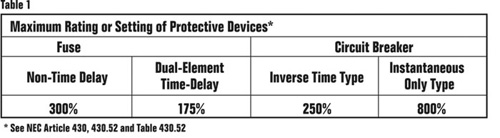
Table 1. Maximum Rating or Setting of Protective Devices*
Too often, installations are not safe due to improper selection, application, or maintenance of overcurrent protective devices. Improper application of a device’s voltage rating, current rating, or interrupting rating can result in equipment damage, injury, and/or death. For example, if a fuse or circuit breaker is chosen with the wrong ampere rating, the electrical equipment may not be protected under overload or short-circuit conditions, allowing destruction of the equipment, fire hazards and possible injury to personnel. If a fuse or circuit breaker does not have an adequate voltage rating, it can rupture while trying to interrupt an overcurrent. Finally, both fuses and circuit breakers can violently explode attempting to interrupt fault currents beyond their interrupting ratings. As an industry, we need to do better at specifying, installing, inspecting, and maintaining proper overcurrent protective device ratings for the application. It starts with understanding the OCPD ratings, how to apply them and Code requirements.
Ampere Rating

Figure 1
At a risk of oversimplification, the ampere rating of a fuse or circuit breaker is the maximum amount of current that it can safely carry without opening, under standard test conditions. Fuses and circuit breakers have a range of ampere ratings. NEC 240.6 lists the standard ampere ratings for fuses and inverse time circuit breakers. Standard amperage sizes of the Code are 15, 20, 25, 30, 35, 40, 45, 50, 60, 70, 80, 90, 100, 110, 125, 150, 175, 200, 225, 250, 300, 350, 400, 450, 500, 600, 700, 800, 1000, 1200, 1600, 2000, 2500, 3000, 4000, 5000 and 6000. Additional standard ampere ratings for fuses are 1, 3, 6, 10 and 601. Manufacturers provide OCPDs in other ampere ratings and the use of these non-standard ampere ratings is permitted. Figure 1 illustrates a 200 A fuse and figure 2 illustrates a 225 A circuit breaker.

Figure 2
In selecting the proper OCPD’s ampere rating for an application, consideration must be given to the type of load and Code requirements. What is interesting is that the Code has so many different rules for determining the maximum fuse or circuit breaker ampere rating for different circuits. There are:
- Static loads such as heating where the normal current stays within an envelope of the full-load current or less, and does not have start-up currents greater than the circuit ampere rating.
- Devices that have momentary inrush currents, such as transformers, where the energizing current greatly exceeds the normal full current rating of the transformer.
- Loads that have high starting currents, such as across the line started ac motors which have starting currents four to six times the normal ampere rating that may persist for several seconds.
- Permitted tap conductor rules where conductors are tapped from larger ampacity conductors without an OCPD at that specific tap point.

Figure 3
The Code requirements have the intent to protect conductors and circuit components at their ampacities. What you find is that fuses and circuit breakers are either intended to provide:
- both overload and short-circuit protection, and are located at the line side of the circuit to be protected. (Examples would be heating and lighting branch circuits.), or
- only short-circuit protection, and are located at the line side of the circuit to be protected. In these cases, another device that is intended to provide overload protection is typically required and can be located further downstream. (An example would be a motor branch circuit.)
NEC 240.4 (2005) requires conductors, other than flexible cords and fixture wires, shall be protected against overcurrent in accordance with their ampacities as specified in 310.15, unless otherwise permitted or required in (A) through (G). There can be other components on a circuit, such as disconnects and contactors, and other Code sections require proper ratings so that overload protection is provided for these other components.
The general rule, for which there are numerous variances, is the ampere rating of a fuse or circuit breaker should not exceed the current-carrying capacity of the conductors. As a general rule, the ampere rating of a fuse or a circuit breaker is selected at 125 percent of the continuous load current. Since the conductors are also typically selected at 125 percent of the continuous load current, the ampacity of the conductors is typically not exceeded. For instance, for a 40 A continuous load, the conductor must be rated to carry 50 amperes (125% of 40A) and a 50-ampere fuse or circuit breaker is the largest that should be used (see figure 3).

Figure 4
As mentioned earlier, there are specific circumstances in which a fuse or circuit breaker ampere rating is permitted to be greater than the current-carrying capacity of the circuit. A typical example is motor circuits; dual-element, time-delay fuses generally are permitted to be sized up to 175 percent (or the next standard size if 175 percent does not correspond to a standard size fuse) of the motor full-load amps. For instance the motor circuit in figure 4 would allow fuses sized at 1.75 x 34 A = 59.5 amps. The next standard size is 60 A. Conductors would be sized (per 430.22) at 34 x 1.25 = 42.5 A minimum. An 8 AWG, 75°C conductor would be selected (50 A ampacity per 310.15 and Table 310.16), assuming the terminations are rated for 75°C conductors. This 60 A time-delay fuse is allowed because the required overload relay or “heater” will be sized 125 percent or less (assuming 1.15 SF motor) of the motor full-load amps and provides the overload protection for the circuit. Since the conductor is also sized at 125 percent of the motor full-load amps, the overload relay is intended to protect the conductor from overloads because it is sized at or less than the conductor capacity. Table 1 is a summary of the maximum ratings for common fuses and circuit breakers for single-phase and three-phase motors permitted per NEC 430.52 and Table 430.52. For this example, non-time delay fuses could be sized at 110 A and an inverse time circuit breaker could be sized at 90 A (for this same 8 AWG, 50 A conductor motor circuit application) [see figure 4].
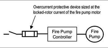
Figure 5
There are additional exceptions, such as when the fuse-switch combination or circuit breaker is approved for continuous operation at 100 percent of its rating.
It is suggested readers review 240.4(A) though (G) for other permitted conductor protection compliance requirements. A few examples are following.

Figure 6
NEC 240.4(A) does not require conductor overload protection for fire pump circuits (see figure 5).
NEC 240.4(B) (2005 edition) allows the next higher standard OCPD rating (above the ampacity of the conductors being protected) to be used for OCPDs that are 800 A or less if the conductor ampacity does not already correspond to a standard OCPD size and if certain other conditions are met (see figure 6).

Figure 7
NEC 240.4(C) requires the ampacity of the conductor to be equal to or greater than the rating of the OCPD for overcurrent devices rated over 800 A (see figure 7). If there are no further changes in the 2008 Code process for this item, this requirement will be changed, allowing for the next standard sizes with certain limitations.
NEC 240.4(D) requires the OCPD shall not exceed 15 A for 14 AWG, 20 A for 12 AWG, and 30 A for 10 AWG copper; or 15 A for 12 AWG and 25 A for 10 AWG aluminum and copper-clad aluminum after any correction factors for ambient temperature and number of conductors have been applied. This is required unless specifically permitted in 240.4(E) through (G) [see figure 8].

Figure 8
One caution is in order. Selecting an OCPD ampere rating following the Code ampacity sizing rules does not ensure short-circuit protection for all circuit components. There are circumstances where further requirements come into play for short-circuit protection. However, this article is unable to adequately cover this topic.
Voltage Rating
Very simply, the voltage rating of a fuse or circuit breaker is the highest voltage that the fuse or circuit breaker is capable of safely interrupting, for all overload and short-circuit conditions at which it is rated to interrupt, under standard test conditions. The proper application of an overcurrent protective device according to its voltage rating requires that the voltage rating of the device be equal to or greater than the system voltage. For instance, a 600-volt fuse or circuit breaker can be used in a 575-V, 480-V, 208-V, or 120-V circuit. However, a 250-volt fuse or circuit breaker is not suitable for 480-V or 277-V applications.
There are two physical aspects to proper voltage rated OCPDs:
- Sufficient creepage and clearance distances to ensure there is not a conductive path or flashover between conductive parts of different phases, phase to neutral, or phase to ground. Figure 9 illustrates the creepage and clearance distances at the terminations of a disconnect. Circuit breakers and fuse holders/disconnects have minimum spacing requirements for specific voltage levels. Adequate creepage and clearance verification, ensuring a product is properly listed for an application, is evidenced by a NTRL mark that the product meets a specific product standard that is suitable for the application.
- The voltage rating of an OCPD is also a function of its capability to open a circuit under an overcurrent condition. Specifically, the voltage rating determines the ability of the OCPD to suppress and extinguish the internal arcing that occurs during the opening of an overcurrent condition. If an OCPD is used with a voltage rating lower than the circuit voltage, arc suppression and the ability to extinguish the arc will be impaired and, under some overcurrent conditions, the OCPD may not clear the overcurrent safely.
OCPDs can be rated for ac voltage, dc voltage, or both. Often an ac/dc voltage rated OCPD will have an ac voltage rating that is different from its dc voltage rating. For instance, some fuses are rated 600 Vac and 300 Vdc. When referencing manufacturers’ datasheets, if the rating is described as 600 V, this rating is typically assumed to be ac. However, product markings should be explicit such as 600 Vac or 600 Vdc.

Figure 9
There are two types of OCPD ac voltage ratings: straight voltage rated and slash voltage rated. The proper application is straightforward for overcurrent protective devices with a straight voltage rating (i.e., 600 V, 480 V, 250 V) which have been evaluated for proper performance with full phase-to-phase voltage used during the testing, listing and marking. For instance, all fuses are straight voltage rated and there is no need to be concerned about slash ratings. However, some circuit breakers and other mechanical overcurrent protective devices are slash voltage rated (i.e., 480/277 V, 240/120 V, 600/347 V). Slash voltage rated devices are limited in their applications and extra evaluation is required when they are being considered for use. This will be discussed under “Voltage Rating—Circuit Breakers.”
Voltage Rating — Fuses
Most low-voltage power distribution fuses have 250 V or 600 V ratings. Other fuse ratings are 125 V, 300 V, and 480 V. NEC 240.60(C) requires the voltage rating of cartridge fuses to be plainly marked on the fuse. NEC 240.61 allows fuses rated 600 V or less, to be used for voltages below their rating. NEC 240.60 (A)(2) allows 300 V rated cartridge fuses to be permitted on single-phase line-to-neutral circuits supplied from 3-phase, 4-wire, solidly grounded neutral source where the line-to-neutral voltage does not exceed 300 V. This allows 300-V cartridge fuses to be used on single-phase 277-V lighting circuits. Some Class T fuses are 300-V rated.
Voltage Rating — Circuit Breakers
Most circuit breakers used in low-voltage, power distribution applications have a voltage rating of either 125 V, 250 V, 480 V or 600 V. NEC 240.83 (E) requires the voltage rating of circuit breakers to be marked and not be less than the nominal system voltage.

Figure 10
NEC 240.85 details special requirements for the voltage rating of circuit breakers such as slash ratings. Some circuit breakers and other multiple-pole, mechanical overcurrent protective devices, such as self-protected starters and manual motor controllers, may have a slash voltage rating rather than a straight voltage rating. A slash voltage rated overcurrent protective device is one with two voltage ratings separated by a slash and is marked such as 480Y/277 V or 480/277 V (see figure 10). Contrast this to a straight voltage rated overcurrent protective device that does not have a slash voltage rating limitation, such as 480 V.
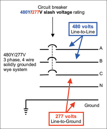
Figure 11
With a slash rated device, the lower of the two ratings is for overcurrents at line-to-ground voltages, intended to be cleared by one pole of the device. The higher of the two ratings is for overcurrents at line-to-line voltages, intended to be cleared by two or three poles of the circuit breaker or other mechanical overcurrent device. Slash voltage rated overcurrent protective devices are not intended to open phase-to-phase voltages across only one pole. Where it is possible for full phase-to-phase voltage to appear across only one pole, a full or straight rated overcurrent protective device must be utilized. An example of an application where a 480-V circuit breaker may have to open an overcurrent at 480 V with only one pole is when Phase A goes to ground on a 480-V, B-phase, corner-grounded delta system. Slash voltage ratings for circuit breakers are addressed in NEC 240.85 restricting their use to solidly grounded systems where the line-to-ground voltage does not exceed the lower of the two values and the line voltage does not exceed the higher value.
Overcurrent protective devices that may be slashed rated include, but are not limited to:
- Molded-case circuit breakers — UL 489
- Manual motor controllers — UL 508
- Self-protected Type E combination starters — UL 508
- Supplementary protectors — UL 1077

Figure 12
Two other special requirements are detailed for the voltage rating of circuit breakers in NEC 240.85:
- A circuit breaker with a straight voltage rating, such as 240 V or 480 V, shall be permitted to be applied in a circuit in which the nominal voltage between any two conductors does not exceed the circuit breaker’s voltage rating (see figure 12).
- A two-pole circuit breaker shall not be used for protecting a 3-phase, corner-grounded delta circuit unless the circuit breaker is marked 1Φ–3Φ (see figure 13).
Interrupting Rating
NEC Article 100 defines interrupting rating as “The highest current at rated voltage that a device is intended to interrupt under standard test conditions.”

Figure 13
The rating that defines the capacity of an overcurrent protective device to maintain its integrity when clearing fault current is termed its interrupting rating. Interrupting rating for fault interruption is primarily related to the fuse or circuit breaker integrity to interrupt the fault current; it is not a rating that ensures protection for all downstream circuit components.
NEC110.9 requires devices that interrupt current to have a sufficient interrupting rating for the current that must be interrupted. Section 110.9 recognizes the difference between interrupting operating current and interrupting fault current. Circuit breakers and fuses are devices intended to break current at fault levels and 110.9 requires them to have an interrupting rating sufficient for the available short-circuit current at their line terminals. Equipment, such as disconnects and motor controllers, intended to interrupt operating current are required to be rated for the current that must be interrupted such as load current or motor locked-rotor current. This article pertains to fault current interruption by fuses and circuit breakers.

Figure 14
Figure 14 shows four sequenced photos taken from high speed filming of a test of a pair of 600-V, one-time fuses where the short-circuit current exceeded the fuses’ interrupting rating. These fuses have an interrupting rating of 10,000 A at 600 V. However, the test circuit was capable of delivering 50,000 A of short-circuit current at 480 V. This is a misapplication since the fuses do not have sufficient interrupting rating for the application. Notice in this test the large amount of destructive energy released by these devices as they rupture violently.
Minimum Interrupting Rating
NEC 240.60(C) states that the minimum interrupting rating of branch-circuit cartridge fuses is 10,000 A. NEC 240.83(C) states that the minimum interrupting rating of a branch-circuit circuit breaker is 5,000 A. A branch-circuit fuse or a branch-circuit circuit breaker must be properly marked if the interrupting rating exceeds these minimum ratings, respectively. These minimum interrupting ratings and markings do not apply to supplemental protective devices such as glass tube fuses or mini-breakers (supplementary protectors — UL 1077).
Figure 1 shows a fuse that has a UL Listing of 300 kA interrupting rating at 600 Vac and 100 kA interrupting rating at 300 Vdc. The interrupting rating for a given circuit breaker typically varies based on the system voltage. Figure 2 shows a circuit breaker with different interrupting ratings corresponding to various application voltage levels.
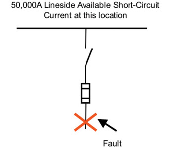
Figure 15
In figure 15 circuit, what interrupting rating must the fuse have?
Answer: at least 50,000 amperes. Classes R, J, T, L and CC fuses have an interrupting rating of at least 200,000 amperes.
Question:In figure 16, what interrupting rating must the circuit breaker have?
Answer:Some value greater than or equal to 50,000 amperes. It is important to realize that circuit breakers come in a wide variety of interrupting ratings. For example, a circuit breaker may be rated 10,000 A, 14,000 A, 18,000 A, 22,000 A, 25,000 A, 30,000 A, 35,000 A, 42,000 A, 50,000 A, 65,000 A, 100,000 A or 200,000 A. In addition, circuit breaker interrupting ratings are dependent upon voltage. Thus, a 480-V circuit breaker may have an interrupting rating of 65,000 A at 240 V, but 25,000 A at 480 V.

Figure 16
Is proper interrupting rating a problem in the industry? Many times the author has had people relate seeing a marked 42 kA panelboard with a 10 kA interrupting rated circuit breaker installed amongst the 42 kA circuit breakers. Or, 10-A IR Class H fuses installed where there is more than 10 kA short-circuit current available. These two examples are serious safety hazards. Many industrials are having arc-flash hazard studies performed for their facilities in order to provide a safer work place for their workers. The author’s firm does flash-hazard studies for industrial, commercial, and institutional facilities and the findings are a bit disconcerting. Numerous situations are being identified where the available fault current exceeds the interrupting rating for installed circuit breakers and fuses. Another industry situation: utilities routinely replace transformers due to greater kVA size required for facilities’ expansion or because the prior unit failed. Often the outcome is higher available short-circuit currents in the facilities which then may result in the installed OCPDs having inadequate interrupting ratings.

Figure 17
To ensure an electrical system is compliant with NEC 110.9 requires knowledge of the available short-circuit current at the line side of each overcurrent protective device. As depicted in figure 17, it becomes necessary to determine the available short-circuit currents at the location of each protective device. The fault currents in an electrical system can be easily calculated if sufficient information about the electrical system is known. However, this article does not address how to calculate the available short-circuit currents. There are easy to use tabular methods, hand calculation methods, as well as software applications that can be used to determine the available short-circuit currents in a system. Also, there are easy to use rules of thumb that may be used in certain situations.
Series Ratings

Figure 18
As if this is not enough to know, there is more about interrupting rating. Generally, a circuit breaker should not be applied where the available short-circuit current at its line side terminals exceeds the circuit breaker’s interrupting rating. This is a requirement per 110.9. However, 240.86 has an allowance for fuses or circuit breakers to protect downstream circuit breakers where the available short-circuit current exceeds the downstream circuit breaker’s interrupting rating. The term given to this is a series rated combination, series rating, or series combination rating. The application of series ratings has many technical limitations and additional Code requirements that must be met for proper application. Series rated combinations allowed per 240.86 should be used sparingly. The most suitable and often the only proper application of series rated combinations is for branch circuit, lighting panels. Interested readers can obtain information from various industry sources on series ratings; the author’s company website has explanatory and application materials on series ratings, including a compliance checklist. Figure 18 illustrates the concept.
Single-Pole Interrupting Capability

Figure 19
The single-pole interrupting capability of a circuit breaker, self-protected starter and other similar mechanical overcurrent protective devices, is its ability to open an overcurrent at a specified voltage utilizing only one pole of the multi-pole device (see figure 19). Multi-pole mechanical overcurrent protective devices are typically marked with an interrupting rating. This marked interrupting rating applies to all three poles interrupting a three-phase fault for a three-pole device. The marked interrupting rating of a three-pole device does not apply to a single pole that must interrupt a fault current at rated voltage.
There are electrical systems with specific grounding methods that may require a three-pole circuit breaker to interrupt fault current at full voltage across only one pole. NEC 110.9 requires an overcurrent protective device to have an interrupting rating equal to or greater than the fault current available at its line terminals. This includes whether the device is interrupting the fault via a single pole or multi-poles. A fine print note was added to 240.85 of the 2002 NEC and 430.52(C)(6) of the 2005 NEC. These fine print notes alert users that mechanical devices, such as circuit breakers and self-protected combination controllers, have single-pole interrupting capabilities that must be considered for proper application. Although most electrical systems are designed with overcurrent devices having adequate three-phase interrupting ratings, the single-pole interrupting capabilities are easily overlooked. The electrical systems where this should be investigated are ungrounded systems, high-impedance grounded systems, and corner-grounded delta systems. These types of systems have long been common for continuous process applications and are becoming more commonly used for other applications in order to reduce the probability of flash hazards. The website of the author’s company has explanatory materials on single-pole interrupting capabilities.
Conclusion
The information in this article Overcurrent Protection Basics, Part II provided information on three important fuse and circuit breaker ratings: ampere rating, voltage rating and interrupting rating. These important criteria lay the foundation for a better understanding of overcurrent protection and code-compliance.