
Many requirements in Article 406 are often overlooked or taken for granted, including many details on exactly how to install and properly use everyday devices that are probably the most used items within our electrical systems. So let’s begin and see how often we say, “I knew that” or “I didn’t know that was in Article 406.” Note that this article is still based on the 2011 National Electrical Code, as many jurisdictions have not yet adopted the 2014 NEC.
First, in order for us to have a common understanding, we need to look at the definitions of the devices we just mentioned. Let’s start with receptacles; a common mistake made is to call a receptacle an outlet. These two terms are not interchangeable. An outlet is defined in Article 100 as “a point on the wiring system at which current is taken to supply utilization equipment.” This could be any point at which power is provided to a luminaire, air conditioner, air compressor, heating unit, etc. As you can picture, many of these are hardwired connections. Receptacles by definition are “contact devices installed at an outlet for the connection of an attachment plug.”
In order to define receptacle, we used another term: attachment plug. Once again looking in Article 100, we find a definition for attachment plug (plug cap) (plug) that tells us it is a “device that, by insertion in a receptacle, establishes a connection” to the conductors feeding the receptacle.
The last term we need to define is cord connector, which is often called by other terms such as female plug or cord receptacle (to name a couple), but the preferred term is the one used by manufacturers and that is a connector body. However, as we have experienced before with the electrical industry, the prevalence of slang terms often means that when you use the proper name, you might get a strange look. Connector bodies are generally made to be installed on flexible cords and allow the insertion of an attachment plug. The most common application is a simple extension cable.
This may seem like basic information. However, we need to make sure we understand exactly what we are talking about and that we understand the terms that are used in the Code and industry in order to learn the Code properly.
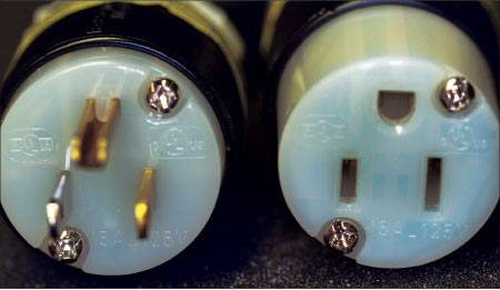
Let’s explore a little bit deeper into the configuration of these devices. If all manufacturers decided independently how they wanted to make their devices, then nothing would work together unless the products you used had the same manufacturer. In order to avoid this situation, the National Electrical Manufacturers Association (NEMA) created a standard based on several common characteristics. The first characteristic is the style, straight-blade or twist-lock, and from there the configuration details are based on the amperage, voltage, and number of phases for the equipment to be connected. One of the best tools an electrician or inspector can carry is a wiring device selector slide rule (available from manufacturers) to assist in the proper selection of a device. If you jump ahead to 406.8 Noninterchangeability and review the NEMA configuration charts, you will see that each application will have a unique design intended to prevent the misapplication of devices, such as mixing of voltages or amperages.
In 406.3 Receptacle Rating and Type, we find some basic but critical rules. First, receptacles are to be listed and marked properly; this includes such things as the voltage, amperage, and manufacturer. Receptacles for use with aluminum wire rated 20 amperes or less shall be properly marked with the CO/ALR marking. This is a critical item to look for as a combination inspector if you find yourself in an older remodel that may have aluminum branch circuit wiring. Since these receptacles cost more than a standard copper-only receptacle, many times the installer will buy the cheaper receptacle that is not approved for aluminum conductors, so keep your eyes open. If you find the even rarer copper-clad aluminum conductors, then make sure you have the proper receptacle marked with “copper-clad” or “cu-clad.”
The last item in 406.3 is the identification of Isolated Ground receptacles. These receptacles are often completely orange in color; however, all that is required by Code is an orange triangle on the face of the receptacle. These are often used when connecting sensitive electronic equipment that may be affected by electromagnetic interference. Providing an isolated grounding source may prevent interference from other equipment within the facility.
Article 406.4 covers general installation requirements, while (A) through (D) deal primarily with grounding. We recognize grounding as one of the most important items in the electrical industry, and proper grounding is essential to the installation and use of receptacles.
One of the features of receptacles and attachment plugs is that the grounding connection must make first and break last, meaning when you insert the plug the ground contact connects first, and when you pull the plug, the ground is the last to disconnect. This feature allows for the safety of having a complete grounding path during the connection and disconnection process.
Getting back to the Code, we find that 406.4(A)–(C) lays out the requirements for grounding, making it generally required for all installations and describing how the grounding connections will be made. As we have often discovered in the Code, there are exceptions; the most common exception is used when working in an existing, older installation where we do not have grounding type receptacles in the first place.
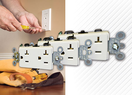
Replacement receptacles are covered in 406.4(D), and we have had a few changes to this section recently. This is one of the articles I always cover in detail for the inspectors and contractors in any class we teach, so we will do the same here.
In 406.4(D)(1), it states that if you are replacing a receptacle where you have a grounding means or an equipment grounding conductor then you must install a grounding type receptacle with the grounding terminal properly connected to that grounding means.
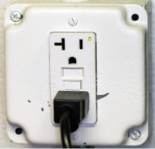
Where we don’t have a grounding means then we follow the language in 406.4(D)(2), which is further broken down into three options. First, you may replace a non-grounding receptacle with another non-grounding receptacle and be done. From time to time, I have seen locations that still stock non-grounding receptacles, so they are still out there. The second method is to replace the non-grounding receptacle with a ground-fault circuit interrupter receptacle (GFCI); then we have to mark it with the following language “No Equipment Ground,” and no grounding connections are to be made to the GFCI or any outlets supplied downstream of the GFCI. The third option allows a grounding type receptacle to be installed, as long as the grounding receptacle is supplied through a GFCI. It shall be marked as “GFCI Protected” and “No Equipment Ground,” and no equipment grounding conductor is permitted to be connected between the grounding type receptacles used in this case.
The next four items covered in 406.4(D)(3) thru (6) are retroactive requirements when replacements are made. First, a GFCI is required to be installed if you need to replace a receptacle in a location that now requires GFCI protection by current code. This requirement was put in place in the interests of providing greater safety in older or existing installations, so receptacles are no longer “grandfathered” in by virtue of being installed before GFCI protection was required.
We have a similar code requirement in 406.4(D)(4) for Arc-Fault Circuit Interrupter (AFCI); it states that when replacing a receptacle that by current codes would have to be AFCI-protected, then you must provide AFCI protection as specified. There are three options: first, install an AFCI receptacle device; second, provide AFCI protection upstream from an AFCI receptacle device; third, protect the entire circuit through the installation of a combination AFCI circuit breaker.
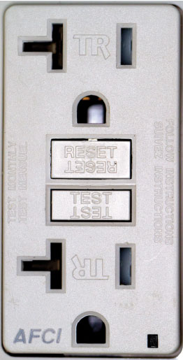
The last two sections of 406.4(D) deal with Tamper-Resistant Receptacles and Weather-Resistant Receptacles. Again, in locations that require these types of receptacles to be installed in the current code, you are tasked with installing tamper-resistant or weather-resistant receptacles when replacing older type receptacles. When the proposal to include the requirement for tamper-resistant receptacles came to the code-making panel, the code panel was presented with statistical facts on how many children had been treated at health care facilities for injuries and burns from insertion of items into receptacles. This information provided a compelling reason for this code addition.
Weather-resistant receptacles are those that are constructed in such a manner as to withstand the harsher environment of the outdoors. As an example, environmental items such as moisture can deteriorate receptacle components like metal mounting screws; this can create an unsafe condition. Also, the compounds used to make the devices must be able to withstand the harsh effects of hot and cold temperatures and UV rays.
Next we come to 406.5 Receptacle Mounting. Generally speaking, in (A) and (B) the one common requirement is that the mounting strap or “yoke” shall be rigidly mounted against the surface or box. We shouldn’t have any of those flexi-flyers or floating wonders, and I think you all can relate to what I mean by those descriptions. I hold my breath every time I go to plug in a piece of equipment and the receptacle wiggles — not knowing if that is a metal box, how close the side screws are to the box, or worse yet, if any of the conductors are not tightened properly and are coming loose or even close to falling off due to the additional movement created by the loose receptacle.
In 406.5(C) we find the requirements for mounting receptacles to what are commonly referred to as industrial covers. These covers are used when we have electrical boxes mounted exposed. These covers match the outside dimensions of the boxes and protrude some depth from the box; the receptacle must mount securely to the cover. Several cycles ago, we added language that required more than one screw to mount the receptacle to the cover. In my opinion, this was one of the best changes made, yet it seems like a very small one. The issue was that the single screw would work its way loose, and the device would simply be floating within the metal box — not a good situation. The requirement for more than one screw helps to prevent this issue and provide a safer installation, as well as cutting down on maintenance issues.
We will do a quick review of the rest of 406.5(D) through (G). There are some very important items here — some basic, some not so basic. First, the face of the receptacle is required to project from a metal faceplate a minimum of 0.015″. If using faceplates that are insulating (such as plastic or nylon), the receptacle faces are allowed to be flush or project. Receptacles installed in countertops or similar locations in dwelling units are not allowed to be installed face up. Please do not confuse a floor outlet as a similar location.
A basic requirement is that no live wiring terminals may be exposed; this seems obvious in today’s world, but a century ago the devices were a little more exposed. The last item in this summary is that we shall not create an installation where we have over 300 volts between adjacent devices when installing multiple receptacles or switch combinations within the same enclosure. Keep your eye peeled for this when doing inspections in facilities where we have a 480-volt system. At times, an identified barrier may have to be used to provide the separation required.
Jumping to 406.7, we find there is a central theme to each of the specific paragraphs in this rule. The message here is that at no time will the exposed prongs of an attachment plug or flanged inlet be energized, unless properly connected to a receptacle or connector body. This is where we often have inventive individuals create or misapply equipment, which can lead to dangerous situations. I have seen extension cords with each end fitted with an attachment plug, so that when one end is plugged in, the other exposed end is energized. These situations often occur when trying to back feed circuits, frequently with the use of generators.
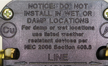
Receptacles in Damp or Wet Locations is what we find in 406.9. A receptacle installed outdoors in a location that is protected from weather or in other damp locations only needs to be covered to make it weatherproof. This is different from wet locations, but what constitutes a protected location? We get a little help here from the language in the third paragraph of 406.9, which states that “a receptacle shall be considered protected from the weather where located under roofed open porches, canopies, marquees and the like”; and the key here is the continuation of the sentence that states that the receptacle shall “not be subject to a beating rain or water runoff.” As you can see, this is a subjective enforcement issue, and we all have seen rain come down at various angles and even sideways at times. The way we enforced it locally in Las Vegas is that we would draw an imaginary 45-degree line from the edge of a patio or porch; anything under this line was considered “wet” and anything above or behind the line was “damp” or “protected.” Although not perfect, this was the best compromise we could find to create a common understanding for contractors and inspectors.
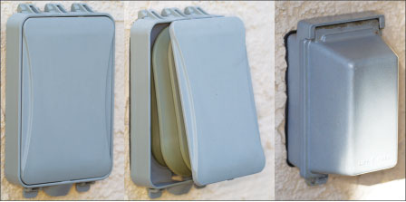
When installed in a location considered “wet,” the protection has to be such that it will maintain the weatherproof rating with or without an attachment plug connected. This requirement has led to what is commonly called “bubble covers.” [These are referred to in the NEC as “extra duty outlet box hoods.”] The issue with these items is that they are at times difficult to operate and often do not pass the test of time for durability. However, we continue to see improvements with these products. There are some exceptions to this code requirement, so please review 406.9(B)(1)and (2).
Another frequent combination inspection issue is covered in 406.9(C), Bathtub and Shower Space. Simply put, “receptacles shall not be installed within or directly over a bathtub or shower stall.” The interpretation and enforcement difficulty often comes when determining what defines the area covered. When I was in enforcement, we tried to make it simple: envision a box that covers the outside dimensions of the tub or shower stall and keep the receptacles outside the box all the way to the ceiling.
Requirements for grounding-type receptacles, adapters, cord connectors and attachment plugs are found in 406.10; however, most of these requirements are covered in the manufacturing process and the product standards, so please review the language on your own as we will not cover it in detail here.
The last item covered in 406 is tamper-resistant receptacles. There have been a few modifications to the requirements for Tamper-Resistant Receptacles in Dwellings Units, and two new locations were added where we have identified the same risk level. As in the 2008 NEC, in dwelling units we are required to install tamper-resistant receptacles in all areas specified in 210.52. There are four exceptions, but I suspect these will not be widely used. The everyday standard replacement device that will be used will be the commonly available design, and that will be tamper-proof due to standardization and economies of scale. Also, as a contractor, stocking non-tamper-resistant receptacles means that you would be taking the chance that your electrician doing the trim might make a mistake and grab the wrong device and install a regular receptacle in an area that requires tamper-resistant. Then you would have a code violation and perhaps a failed inspection if caught by the eagle-eyed inspector.
The two locations that were added in Article 406 related to tamper-resistant locations are found in 406.13 and 406.14. These are interesting to me as we made our dwelling units safer for children in a previous code cycle, but forgot that the same children also occupy guest rooms of hotels or motels, or better yet, childcare facilities. This situation is one of the reasons why the code is always being revised, to catch little items that just get missed. If you know of an item that you think has been missed or can be improved, please take the opportunity to submit your own code change proposal. Go to www.nfpa.org for details.