Continuing with our journey through the National Electrical Code (NEC), let’s skip to Article 695 Fire Pumps. I am not going to cover Article 690, Solar Photovoltaic (PV) systems, mainly due to the fact that so many articles have been written regarding PV, including many published within the covers of this magazine in the last several years.
Fire Pumps
The scope of Article 695 Fire Pumps covers the installation of electrical power sources, interconnecting circuits, and switching and control equipment dedicated to fire pump drivers. This article does not cover the performance, maintenance, or testing required over the life of the fire pump. There is no process for enforcement in the NEC that can cover the system after installation, but we have other codes that deal with those issues.
A fire pump is used when the building code requires sprinkler protection based on the occupancy and the building type. The fire pump is required to provide service when needed and continue until the sprinklers are no longer needed or the pump has died doing its job. Therefore, we need a source of power that is reliable and can handle up to the locked rotor load of the pump. The code outlines what it considers reliable in Article 695.3. This may be a combination of sources, such as an individual source and an on-site generator as outlined in 695.3(B)(2). If fed from the utility, the source of power for a fire pump may be a completely separate service, or it may be connected ahead of the main disconnect of a service. Some special requirements as outlined in 695.3(A)(1) must be met. Often these requirements are not met when trying to install a fire pump to an existing service, so please pay special attention in this situation. Try to be proactive and check that these requirements are being considered during plans check or first inspection on site to avoid a huge situation later.

The normal source of power must be capable of supplying locked rotor current for the pump, and remember that current may be close to 6 times the full load amperage. The label on the fire pump should indicate the locked rotor current. The alternate power source consisting of a generator only has to have sufficient capacity to allow normal starting and running of the unit. If the generator is able to have some load shed during operation of the fire pump, it may be sized a little smaller, with the assumption that optional standby loads will be shed if the fire pump is running, see 695.3(D).
The requirements for disconnects and overcurrent protection are very different than our normal requirements, and they are found in 695.4(B). Care must be taken here to make sure that they are limited to just one between the source and the fire pump controller, and that they are also able to meet requirements similar to those for the normal source, including being able to carry the locked rotor current. The overcurrent protection for the generator must be sized to handle the instantaneous pickup of the full pump room load, which may include some additional equipment, such as a jockey pump.
Conductor installation from the normal source shall be routed outside the building as noted in 695.6, with a few alternative ways as described there. Feeders from the disconnect or conductors from the generator have four options, however the two most common are to route them outside the building under the slab, or use a fire rated wiring method rated for 2 hours protection. Sizing must be done according to 695.6(B); generally speaking this will be 125% of the fire pump and all other associated motors plus 100% of the accessory equipment related to the fire pump equipment. For the pump itself, conductors must comply with 430.22 (mainly 125% for standard motors). However, voltage drop must be taken into consideration. This is one of the few code areas where we have a requirement for voltage drop. The reason for this is that if the voltage drops too far, the current of the motor will rise and can decrease the life of the equipment. Please see 695.6(D) for the approved wiring methods to be used between the controller and the pump motor.
This probably seems obvious, but we do not want any ground fault devices in the circuits related to the fire pumps. Remember, the pump equipment may need to operate until it destroys itself in order to continue protecting the building.
Once the feeder circuits get into the fire pump room, then the requirements found in 695.6(H), (I) and (J) need to be followed; these deal with proper wiring transitions and methods. In 695.7, the voltage drop issue is again mentioned and this is where it can become difficult. As an inspector, how are we to verify that the voltage during start up does not exceed 15% or 5% with the unit operating at 115% of the full load current? We are limited by available equipment and time to verify this inspection requirement, so perhaps you need documentation from the engineer of record that this has been addressed and the proper adjustments made to the design to ensure these requirements are met. The professionals who do these types of installation should be able to verify that the installation does not exceed the voltage drop limits.
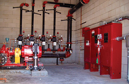
Typically we find a tap ahead of the main service with wiring outside the building that feeds to the fire pump controller; we also find a feeder from the emergency generator that is routed outside or is a fire-rated wiring method. Both of these terminate inside the fire pump room at the fire pump controller, a listed piece of equipment specifically designed for this purpose. Get with your local fire pump supplier and have them show you the equipment and how it functions, this will make you a better inspector for these systems.
Emergency Systems
Our next stop in the code is Article 700 Emergency Systems. From the title, it is apparent that these are important installations and require great care when installing and inspecting. This is reinforced by the scope, definitions and the informational notes found in 700.1 and 700.2. The informational note actually sums up the article and explains that these systems are required in larger facilities where we have larger occupancy levels, such as places of assembly (hotels, theaters, sports venues and health care facilities, for example). They are required in order to minimize the panic during an emergency and to provide safe egress for the occupants. In addition to the obvious need for emergency illumination, these systems may also power ventilation (where needed to maintain life), fire detection and alarm systems, elevators, fire pumps, communications systems and certain industrial operations that would create a life safety hazard if they were suddenly shut down.
These systems generally have a generator for the emergency supply source; and, therefore, will require testing and maintenance. Most building departments do not have a follow-up process in place. Generally, once the final inspection is done and the certificate of occupancy has been issued, the authority having jurisdiction (AHJ) doesn’t come back. We often had issues when an existing facility would build an addition; we would ask for another witness test and they would balk, and when it was finally performed we often would find that the system would not operate properly or at all. So please read 700.3 and see if you can find a way to get enforcement for the maintenance testing of these systems.
The capacity of the emergency system is covered in 700.4. You will find that one generator may supply the emergency, legally required standby and the optional standby systems, but this is only the case if the system has automatic load shedding to insure that the emergency system has the highest priority and will always be operational.
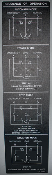
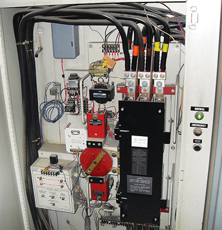
Emergency systems have transfer switches that will automatically provide power from the generator with the loss of normal power, and this transfer has to happen within 10 seconds as mentioned in 700.12. This can be a challenge because the generator has to start and become stable, and then the transfer switch has to roll over.
A special item to note is that we do not want a ground-fault protection system to interrupt our emergency system; instead we use a ground-fault detection system to indicate a ground fault but not to open the circuit. This will only apply to solidly grounded systems, more than 150 volts to ground that are 1000 amps or more in size; see 700.6(D).
Circuit wiring for these systems must also meet the requirements of 700.10, which covers identification and the need to have separation from other systems within the facility. There are five conditions that allow us to mix the normal power and the emergency circuits found within Article 700.10; these actually make sense when you read and think about each one. Usually we find the emergency systems identified in red, where the boxes and conduits are all identified by that color. Colored EMT can now be ordered directly from the manufacturers.
Feeder Circuit Wiring shall be protected as required in 700.10(D). If there is a fire suppression system (generally sprinklers), the sprinklers have to cover the spaces where the conduit is actually located, so this will result in sprinkler heads sometimes installed above t-bar ceilings and similar locations if the feeder passes through any isolated building locations. There are other methods for the protection of the feeders, but do your due diligence and make sure the system you are using is a currently listed system with the proper certifications from a testing agency. In the last few years, there have been several changes resulting in newer requirements for these systems. Be on your guard when using or inspecting these systems and make sure they are allowed.
In 700.12 we find the Sources of Power requirements. There are several methods listed, but I will mention the two most common. The first is prime movers powered by internal combustion engines (better known as an emergency generator). These have to have an onsite fuel storage supply that can provide a minimum of 2 hours of run time under full demand load. We used to have our units load bank tested before we would approve one on the project; the test would be worst case, and we asked for a two hour full load test.
The second most commonly used is the Unit Equipment which is simply the battery emergency lights and exit lights. Often these may be part of a normal fixture, as an optional addition to illuminate the fixtures partially during power outages. An example is a lay-in troffer with an emergency ballast. These have to maintain 60% illumination output for 90 minutes. Using these systems requires that the branch circuit feeding the unit equipment is the same as the one feeding the normal lighting in that area and connected ahead of any switches providing controls for that area. This is to insure that if something happens to the circuit, you will know it because the normal lighting will be out. If you have an uninterrupted area that is large enough that it will use 3 circuits or more, then the emergency lights may be on a dedicated circuit for that area, as long as the circuit originates from the same panel as the other branch circuits and has a lock-on device to make sure it isn’t inadvertently shut off.
Part IV of Article 700 deals specifically with Emergency System Circuits for Lighting and Power. One point of interest here is that 700.16 states that these systems shall be designed in such a way that the failure of any individual lighting element cannot leave any space in darkness where emergency illumination is required.
Note that some of our lighting methods do not provide full illumination due to their warm up time. Also, for some lamps, if they are running and have a loss of power for up to 10 seconds they will not re-ignite until they cool off and re-strike. Care must be taken to insure that we have a proper amount of lighting when needed where emergency illumination is required.
Part V deals with Control — Emergency Lighting Circuits, which mainly is switches and dimmers. The key issue here is that when needed, the emergency lights will illuminate no matter what when we have a loss of power, even if they may be switched or dimmed for any reason. Please read to get the details, but one location to consider is theaters, where they dim the lights for movies and when power is lost the emergency lights will come on to their proper level.
The last item to cover in Article 700 is the need for Selective Coordination found in 700.28. The concept is that the overcurrent devices throughout the distribution system that feed the emergency system shall be selected in such a way that any fault or overload will only open the overcurrent device directly ahead of the abnormal operation. This is not as simple as it seems, since the overcurrent devices may have fault curves that may not provide the separation needed to only operate the closest device and not the upstream unit also, or in the worst case, the facilities main. Please do not minimize this portion of the code. Selective Coordination has been in Article 700 since 2005, but it has not been widely enforced. So please reach out if you don’t understand what it is and how to get enforcement. I would be happy to provide more information regarding this requirement and how to comply with it. It is one of the items that I have taken a special interest in due to the type of occupancies I was responsible for while enforcing the code in Las Vegas.
Legally Required Standby Systems
Article 701 is Legally Required Standby Systems. Again, the informational note gives us the best description of these systems. These include such loads as heating and refrigeration, communication, ventilation and smoke removal systems, and sewage disposal, to name a few. You may notice that these are not really the systems we would classify as life safety, which are those needed to safely get people out of a facility. Instead, these are loads that may be needed during a prolonged period to maintain the minimal operation of a facility.
These systems have very similar requirements to Article 700, but they only need to be restored within 60 seconds of power loss. This allows for a stabilizing effect on the generator. If we transfer everything all at once, the generator has difficulty handling the sudden load, and the voltage may fluctuate while it tries to re-stabilize after the load has been applied. By staging the loads, this issue is minimized.
The main difference is the nature of the systems powered. Take the time to review the code and compare the differences between 700 and 701.
Optional Standby Systems
The last item to cover is Article 702, which is Optional Standby Systems. These are the systems that are added to the backup power source, generally at the request of the owner for a variety of reasons. I will let you review Article 702 on your own, but I will share with you how these generally were used in the locations I inspected. The owners of the casinos always wanted the gaming machines to be on the “emergency systems.” This was due to the fact that to them every minute these machines were not operational, they were losing money. So we always had to keep a close eye on the designs to ensure that such items were only connected to the optional system, and that they were the first to shed if the emergency system needed more power.
I should also note that in some cases you may find special types of emergency lighting. One such situation is in the State of Nevada, where the Gaming Commission has the requirement that over any open gaming tables there can be no interruption of the lighting. Therefore, they are on UPS systems. The reasoning is that during the up to 10 seconds of darkness during a normal emergency transfer, a person can grab a lot of money and/or gaming chips.
This brings us to a close of the portions of the code I wanted to share for combination inspectors. I’ve written articles on these subjects for the last 5-½ years, 33 articles in total, all with the intent of providing details that will assist those inspectors who are not from an electrical background. I hope the articles have been helpful and beneficial to those of you charged with enforcing the NEC, and I want to thank you for following along for the last few years.