Nearly every week, I get calls and e-mails from inspectors, plan reviewers, photovoltaic (PV) professionals, engineers, and electricians asking about areas of PV system installation that are not clearly addressed in the National Electrical Code (NEC). Over the years, some of these questions come up repeatedly, while others are unique. This article provides some insight into the most frequently received questions and opens the discussion on items that may lead to clarifications and changes in the Code.
Utility Connections at Existing Service Entrance Panels
Meter-Main Combo Panel
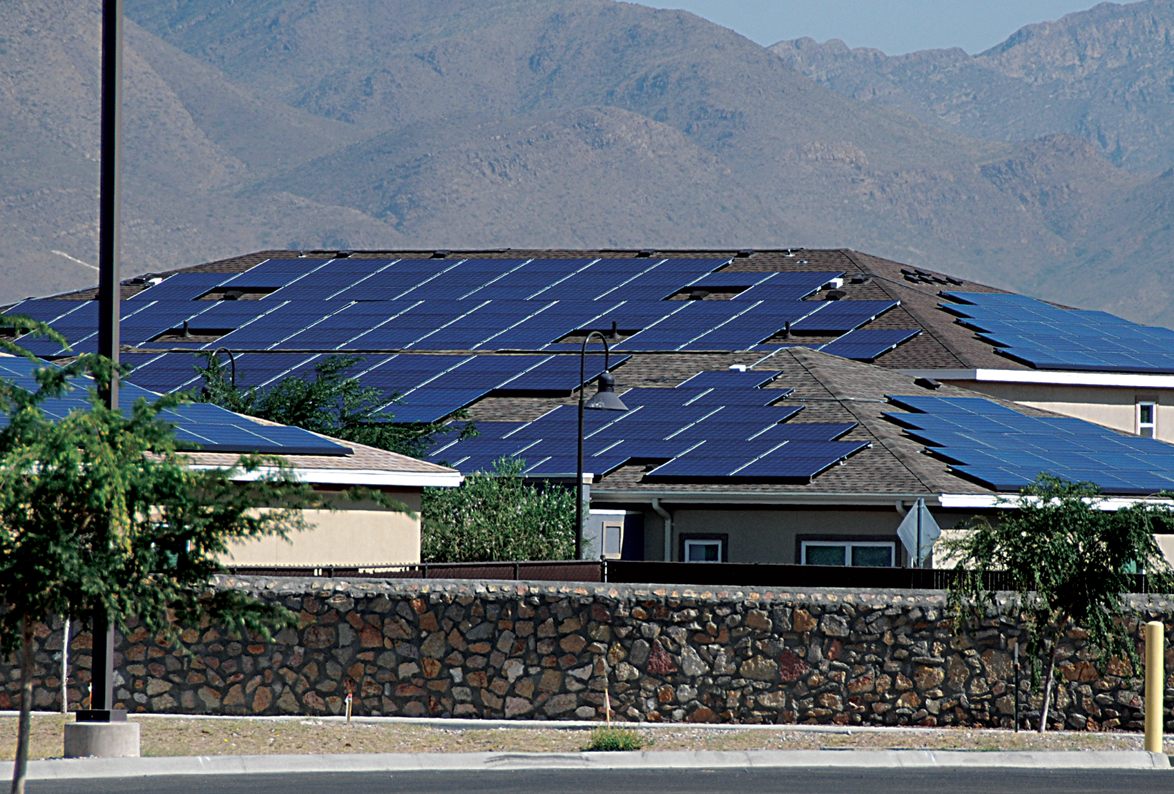
The meter-main combination panel is quite common in many sections of the country (photo 1). These panels have a meter socket in the same enclosure as the main breaker, and some may also have positions for a few load breakers. While there may be exposed, readily accessible busbars or conductors between the meter socket and the main breaker/service disconnect, it is not legal to tap these circuits to make a supply side PV connection [705.12(A)]. Doing so would violate the listing on the equipment, which in turn violates Section 110.3(B), which requires that all listed equipment be used in accordance with the instructions furnished with that listed equipment and any restrictions associated with the listing.

Occasionally, the manufacturer of the meter-main combo may provide instructions and hardware to make such a connection. However, a field inspection by a nationally recognized testing laboratory (NRTL) — the listing NRTL or other NRTL authorized by OSHA to make such inspections — may be required by either the manufacturer or the authority having jurisdiction (AHJ). In some areas, the utility considers the circuit between the meter socket and the service disconnect/main breaker to be utility property and does not allow connections under any circumstances.
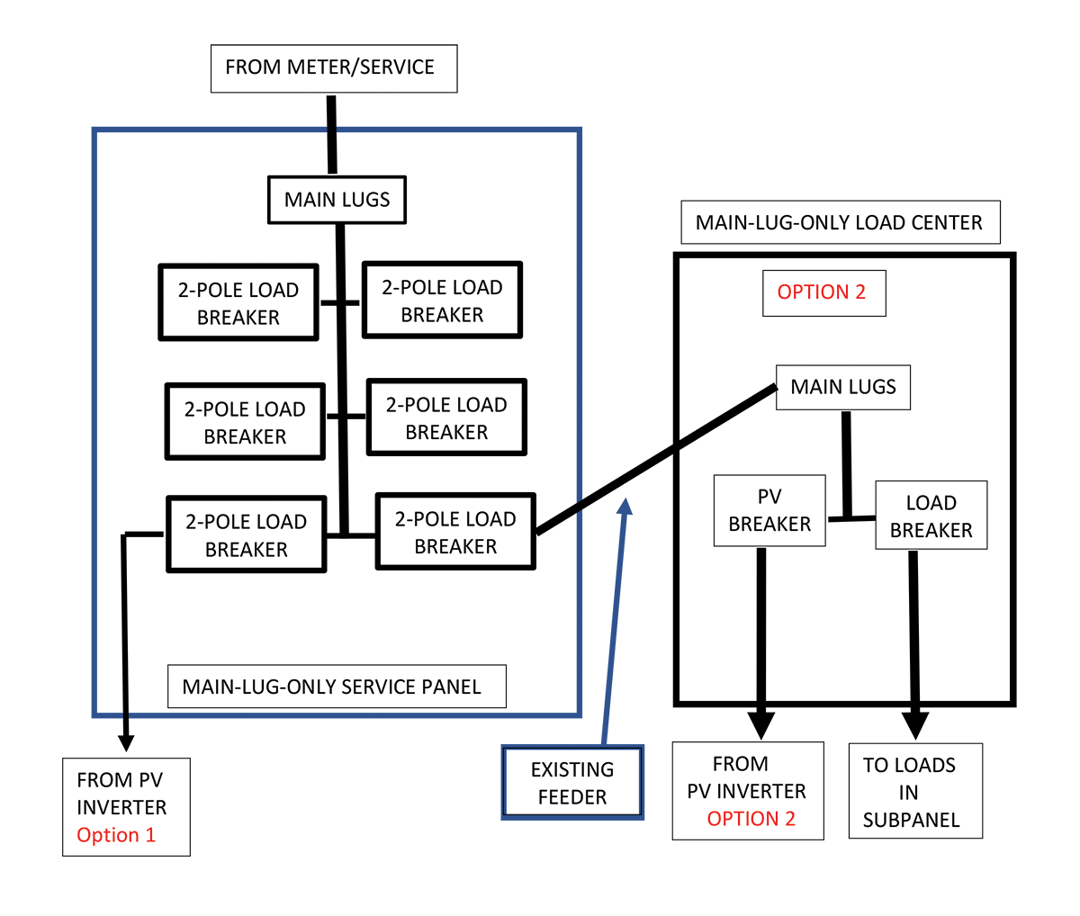
If the meter-main combo has load breaker positions in the enclosure, then if one of these is not being used, a backfed PV breaker may be installed (see figure 1, option 1). Since this breaker and the PV connection are on the load side of the service disconnect/main breaker, the PV connection becomes a load-side connection and the requirements of Section 705.12(B) apply.

In a typical meter-main combo panel, the main breaker has the same rating as the busbar in that panel. Load breakers and the PV breaker, if any, are connected to that busbar. In this situation, Section 705.12(B)(2)(3)(b) would apply and the backfed PV breaker must be at the end of the busbar most distant from the main breaker connection. Also, the 120 percent rule would apply where the largest backfed PV breaker would be 20 amps for a 100-amp busbar, 25 amps for a 125-amp busbar and 40 amps for a 200-amp busbar.
An example of the math leading to these restrictions is:
Take 120% of the busbar rating minus the main breaker rating equals the maximum rating of backfed PV breaker.
For the 200-amp busbar with a 200-amp main breaker:
1.2 x 200 – 200
= 240 – 200
= 40 amps, the maximum rating for the backfed PV breaker.
The Code actually requires that 125 percent of the rated PV inverter output current be used in these calculations, but this usually translates to the breaker rating since the breaker must be at least 125 percent of that rated PV inverter current.
Some meter-main combo panelboard manufacturers make these devices with interchangeable main breakers. While there may be a 200-amp busbar, 150-amp and possibly smaller main breakers may be used. Careful assessment of the loads for the entire building must be made to ensure that the originally installed main breaker was oversized and can be replaced with a main breaker with a lower rating. In all cases, the manufacturer’s instructions and labels must indicate that this is allowed. Using a lower rated main breaker may possibly allow a larger backfed PV breaker.
Here is the math for a 200-amp meter main combo panel with a permitted and allowed 150-amp main breaker.
1.2 x 200 – 150
= 240 – 150
= 90 amps, the maximum rating for the backfed PV breaker.
No Breaker Positions Available—Connect at Remote Subpanel. If there are no open load breaker positions in the meter-main combo panel, two options are possible. First, the load side PV connection may be made at an existing subpanel being fed by the meter-main combo, but all of the 705.12(B)(2)(3) requirements must be met in the meter-main combo panel and the subpanel.
In the meter-main combo panel, the breaker feeding the subpanel must be the most distant from the main breaker on the busbar. The same requirement applies in the subpanel. The backfed PV breaker must be located on the busbar as far as possible from either the subpanel main lugs or the subpanel main breaker. Moreover, the 120 percent applies to the subpanel busbar, subpanel main breaker (or breaker feeding the subpanel in the meter-main panel) and the maximum allowance for the backfed PV breaker.
Here is an example:
A 200-amp meter-main combo panel has a 200-amp main breaker and a 100-amp breaker protecting a feeder to a 100-amp remote subpanel. The 100-amp breaker is moved to the most distant location from the main breaker by swapping breaker positions in the meter-main combo. It is assumed that the feeder to the subpanel is rated at 100 amps or more as required by Code. The 100-amp subpanel is a main-lug-only subpanel. The 120 percent rule in 705.12(B)(2)(3)(b) would allow up to a 20-amp backfed PV breaker as long as that breaker could be placed on the busbar most distant from the main lugs on that busbar. No changes would be required in the size of the feeder because any PV generated currents would oppose the utility currents and reduce the overall current in both the feeder and in the meter-main busbar.
Feeder Tap with New Panelboard. A second method of connecting a PV system to an existing meter-main combo panel would be to tap one of the feeders from the combo panel in a convenient location—anywhere from adjacent to the combo panel or near the remote load center (see figure 1, option 2). In each case, the existing feeder from the point of connection of the PV system to the remote panel must be protected from overcurrents that might originate from both the utility and the PV system. Section 705.12(B)(2)(1)(a) and (b) gives the options, and in most cases, it is not desirable to use option (a) because it is fairly difficult to replace the entire feeder to the remote location and upgrade the subpanel rating. Option (b) is used more frequently.
The easiest way to make the tap connection would be to add a small main-lug-only panelboard with at least two breaker positions at the point where the PV output circuit is to be connected to the feeder. One of the breakers protects the remainder of the feeder to the remote panel, and the other breaker serves as the PV inverter ac output breaker.
Here is an example:
A 200-amp meter-main combo panel has a 125-amp breaker feeding a remote 125-amp main-lug-only subpanel. The 125-amp breaker is in the correct position at the most distant location on the meter-main busbar. A 125-amp main-lug-only panelboard (load center) would be installed adjacent to the meter-main combo, and the feeder routed through this panelboard with the circuit from the 125-amp breaker routed to the main lugs in the new panelboard. The continuation of the feeder to the remote subpanel is made by connecting this circuit to the output of a 125-amp breaker in the panelboard. A PV inverter has a rated output of 15 amps, so a 20-amp breaker would be installed in the new panelboard to connect the PV system output to the feeder.
Math: 15 x 1.25 = 18.75, round up to 20 amps (per Section 690.9).
Using the 120 percent rule would allow up to a 25-amp backfed PV breaker to be installed in this new panel as noted previously. All parts of the feeder are now protected from overcurrents, and none of it has to be replaced or upsized.
With this added subpanel, it would also be possible to install a 200-amp new panelboard and use up to a 115-amp backfed PV breaker while meeting the 120 percent rule in the new panel and not overloading the feeder.
Math: 1.2 x 200 – 125
= 240 – 125
= 115 amps allowable backfed PV breaker.
The 125-amp breaker would still be protecting the downstream feeder to the remote subpanel. The upstream feeder, also rated at 125 amps, would never see the sum of the high PV currents and any utility currents coming through the 125-amp breaker in the meter-main combo panel. Utility currents in this feeder would be reduced by any PV currents flowing back to the meter-main panel because they would oppose each other and lower any currents below 125 amps.
It should be noted when calculating these breaker values, that the position of the added breakers and their ratings protect the various conductors and busbars from overloads (where future loads on the building are increased unknowingly) and from short circuits that may occur in the wiring.
Main-Lug-Only Service Panels with Six Main Breakers
Unused Breaker Position. These types of panels are found throughout the country and pose some issues in connecting a PV system (see photo 2).
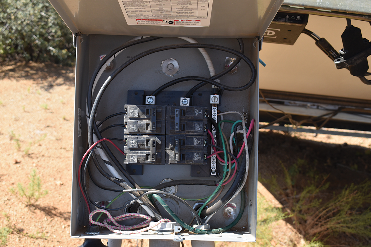
The following applies only to the situation where meter/service conductors are connected to the main lugs. In many cases, the panelboard label requires that if the device is to be used as service equipment, one of the breaker positions must be used as a main breaker/service disconnect. In this case, the other breaker positions become load-side connections if used for the PV backfed breaker, and 705.12(B) applies. The easiest, but somewhat uncommon, situation occurs where one of the six main breaker positions is unused. This unused breaker position may be in any of the six breaker positions, and the use of a backfed breaker in this position constitutes a supply side connection [705.12(A)]. The backfed breaker may be any rating up to the rating of the panel busbar or the service if allowed by the panelboard manufacturer. See caution below.
An example:
A 200-amp main-lug-only service panel has an empty breaker position. The service and the panel busbar are both rated at 200 amps. A 200-amp backfed breaker (if allowed and not restricted by the panelboard instructions) may be installed in the open position. A 200-amp breaker allows for a PV inverter connection with an inverter output rating of 160 amps (80 percent of 200 amps). However, be advised that many of these panels do not allow a breaker rated at the full busbar rating. This is done because the actual loads on such a panel busbar must total less than the busbar rating as required by sections of Articles 230 and 240 and elsewhere. See the extensive discussion in the NEC Handbook for Section 230.90 and Exhibit 230.24. Also note that Section 705.12(A) restricts the sum of the ratings of all overcurrent protection devices for power production sources to be no greater than the rating of the service (see figure 2, option 1).
A word or two of caution about using a large PV backfed breaker in a main-lug-only service panel: although not presently a Code requirement, it is suggested that the larger (approaching the busbar rating) backfed PV breaker be located as far as possible from the main-lug utility input. This prevents PV currents from adding to utility currents under high PV production coupled with high loads and possibly overloading the busbar. The PV currents will oppose the utility currents in the busbar and lower the total busbar current.
Tap the Feeder. In situations where there is no empty breaker position, a feeder from an appropriately sized breaker may be tapped by installing a new panelboard adjacent to the existing service panel as described above. If the short length of feeder between the service panel and the added new panel is increased in ampacity accordingly, an existing breaker for that feeder may be increased to allow larger amounts of backfed PV. The new panelboard would include a breaker rated at the same size as the original feeder breaker and would be used to protect the downstream section of the feeder (see figure 2, option 2).
Summary
Although the NEC does not specifically address PV connections to these common service panel installations, close scrutiny to the various other requirements in the Code can determine how to make these connections safely. Inspectors need to be aware of these situations and how they are being addressed by the PV installers. Future changes in the NEC may clarify these allowances and restrictions.
For further information, contact John Wiles, Southwest Technology Development Institute, New Mexico State University, (575) 646-6105, jwiles@nmsu.edu.