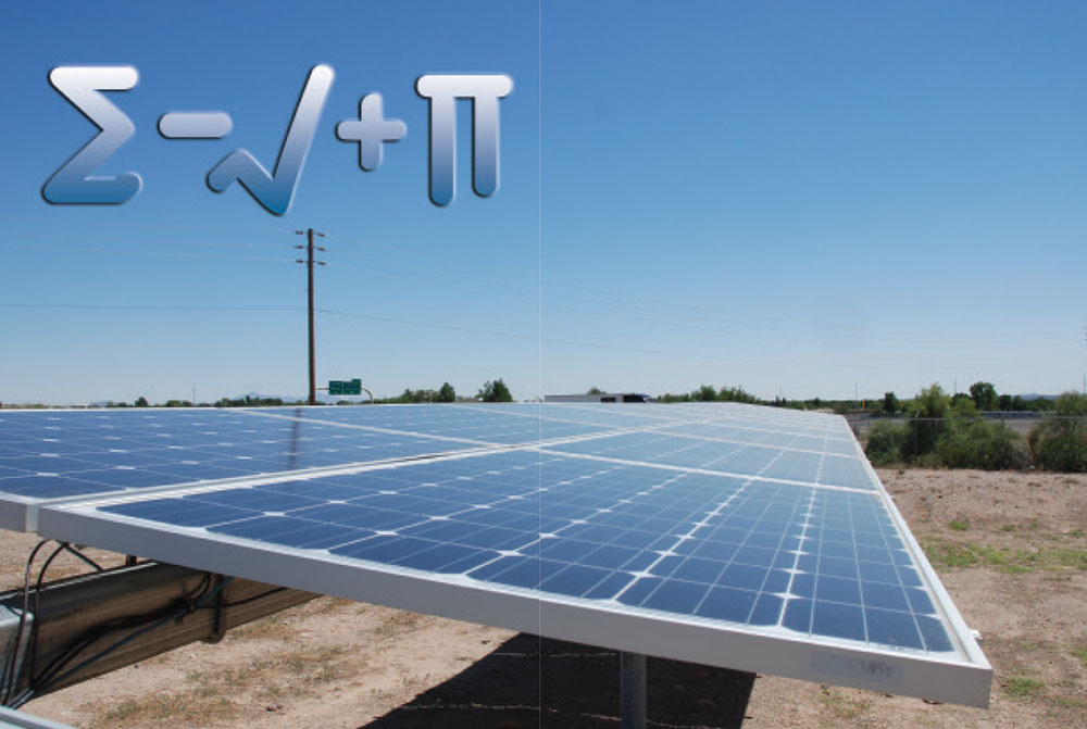
DC Modules
Output varies. As addressed in the previous article in this series, the direct current output of a dc PV module varies with the sunlight intensity, the temperature of the module, and the load connected to that module. These varying output characteristics are significantly different from the relatively constant voltage output of the normal, widespread ac electrical system supplied by a utility; an electrical system that has driven NEC requirements for more than six decades. Hence, we have Articles 690 and 705 that will allow us to deal with the Code requirements unique to PV systems.
PV systems redefined. In the 2017 NEC, PV systems were more narrowly defined as those circuits dealing specifically with the PV system from the module to the PV system disconnect which is the interface point with other types of electrical power systems such as the utility or an energy storage system (ESS), also known as a battery bank. Although many of us think that the inverter in a standalone system or the multimode inverter in an ESS/utility-interactive system and the batteries are part of the PV system, these devices are no longer included in the definition of the PV system. See Figure 690.1 in the Code for a graphic description of what is now included in the definition of PV system components. These circuits do include dc and ac circuits and the utility interactive inverter as well as the ac PV module.
Continuing with the dc PV module, let us examine the voltage output characteristics. This voltage, either unloaded in an open-circuit condition or loaded in a closed-circuit condition, will typically vary with the module temperature. That temperature is affected by the intensity of the sunlight hitting the modules, the ambient temperature and the wind speed. At night (a condition of not much interest), the module temperature will generally be the same as the local ambient air temperature. Without wind, as the sunlight starts impinging on the module surface, that surface will heat up and on a sunny day on a roof top, the ambient temperature in the vicinity of the PV array may easily reach 40°C (104°F) to 50°C (122°F) or higher when the outside air temperature (ambient temperature at the local weather station) may be only 30°C (86°F). We should get used to using temperature as measured in degrees Celsius (C) since many module specifications and Code tables use the metric measurement system. With the no wind, air temperature on the roof at 40-50°C and sunlight (on a bright sunny day) at an intensity (irradiance) of 1000 watts/square meter (W/m2) can cause the module temperature to be 65–75°C and even higher at higher ambient temperatures and brighter sunlight.
Module ratings. The ratings of a PV module include the open-circuit voltage (Voc), maximum-power operating voltage (Vmp), short-circuit current (Isc), current at maximum power (Imp), and maximum-power output (Wmp). Because these parameters vary with the environmental conditions mentioned, the PV module rating is specified as a set of fixed numbers at a set of internationally accepted standard test conditions. The standard test conditions (STC) include a module/cell temperature of 25°C (77°F), a solar irradiance of 1000 W/m2, and an air mass density of 1.5. The air mass density is a factor relating to the spectrum of the sunlight around solar noon and will not be addressed further.
Open-circuit voltage. One of the more critical module parameters is Voc because this voltage determines the required voltage ratings of the module circuit conductors, the disconnects in the module circuits, the overcurrent protective devices and other equipment that the module circuits are connected to.
As the module heats up, the open-circuit voltage (Voc) will go down as an inverse function of the temperature. This value of this inverse function will vary somewhat with module technology such as crystalline, polycrystalline, and various thin films (amorphous silicon, CdTe, CIGS, and others).
For a typical crystalline PV module, the open circuit voltage will vary about 0.4% per degree C change in temperature from the value at the STC temperature of 25°C. As the temperature goes below 25°C, the module Voc will increase above its standard test condition value. This is a critical factor in designing, installing and inspecting a safe and durable PV system.
Modules, depending on the internal connections of cells in series and/or parallel, will have differing Voc at STC. These may be about 17 volts, 34 volts, 68 volts and other values. When modules are connected in series to get the operating voltage up to a value necessary to operate the connected equipment (typically a utility-interactive inverter), the open-circuit voltage may range from a low of 17 up to 600 volts in dwellings, up to 1000 volts in commercial installations and even 1500 volts in utility-scale systems. The Code establishes requirements that allow us to deal with these widely varying, temperature-dependent open-circuit voltages in a manner that prevents them from exceeding the upper limits just mentioned, even in the coldest expected weather. Welcome to Section 690.7.
Lowest expected temperature. Ah, the lowest expected temperature—a controversial subject to say the least. Some PV system designers/installers use the historical record lowest temperature in a particular location, and while this may be relatively easy to obtain, it may not represent the current trend in low temperatures when climate changes are considered. After all, in the last several years, each subsequent year has had a higher average temperature than the preceding year. The Code mentions, in an Informational Note, a source of climate data that gives averages and percentages. This is the Extreme Annual Mean Minimum Design Dry Bulb Temperature found in the ASHRAE Handbook — Fundamentals. Another method that might be used, is to find the lowest annual temperature over the last ten years or so and plot them to determine if there is any trend that can be used to predict the future low temperature. A search of the Internet will reveal sources of climate data for numerous locations.
The local jurisdiction and the PV designers/installers in an area should jointly select a low temperature to be used in PV system designs, while keeping in mind that microclimates in the region may modify that number.
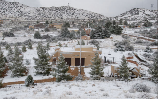
A case study. Unusual climatic events may result in temperatures below the selected number for the lowest expected temperature as happened in Southern New Mexico and West Texas a few years ago. In this region, the PV design temperature used for the lowest expected temperature is 14°F (10°C), but one February day, a cold front from the arctic resulted in temperatures of -2°F (-19°C) for several days.
What was the impact of using an expected low temperature that was much higher than the actual low temperature? Many systems in the area were designed so that at 14°F, the open-circuit voltages would not exceed 600 volts on the string inverter systems. In normal day-to-day operation, the PV inverter will never see the open-circuit voltage because as the sun comes up, the inverter starts peak-power tracking and holds the voltage at the peak-power point which may be 10-15% below the open-circuit voltage. Additionally, as the sun rises, the PV modules begin to heat up and the open-circuit voltage decreases. Although this -2 degree day was sunny and clear, the winds were fairly high in the morning so there was little array heating, resulting in a Voc well above the 600-volt limit on the equipment. The inverter normally will not be subjected to Voc on the input unless the dc PV disconnect is opened or the utility loses power and the inverter shuts down—allowing the connected array to go to Voc. Unfortunately, the local utilities were not prepared for temperatures this low and frozen cooling systems and natural gas shortages for reserve and peaking generators resulted in rolling blackouts throughout the area. Fortunately, these blackouts of utility power happened in the afternoon and with reduced winds, the PV array temperatures had risen to a value that kept most array open-circuit voltages below 600 volts. Little damage was reported on the PV systems in what could have been a very expensive disaster.
Incidentally, many PV inverters record the highest voltage that they have been subjected to, and the factory is usually unwilling to offer warranty repairs when the maximum rated input voltage has been exceeded.
Using the lowest expected temperature. Where silicon PV modules are being used, NEC Section 690.7 allows Table 690.7 to be used with the lowest expected temperature to determine a multiplication factor that can be used to modify the rated open-circuit voltage at STC. This factor can be used either on the module Voc or the string Voc to determine the higher Voc at the lowest temperature. Section 690.7 also allows the module temperature coefficients for Voc to be used where they are available and those temperature coefficients must be used for thin film and other non-silicon module technologies. In most cases, the module temperature coefficients will yield a more realistic value of the cold weather Voc because the table is somewhat conservative and is based on a worst-case temperature coefficient of about -0.4%/°C. Let’s calculate a Voc using an actual Voc module temperature coefficient for a -40°C/-40°F expected low temperature that might occur in one of the northern states.
A typical Voc temperature coefficient may be given as a percent change in Voc per degree Celsius (e.g. -0.3%/°C) or as the actual voltage change in millivolts per degree Celsius for a single module (e.g. -167.4mV/°C). Many prefer to use the percentage change since it can easily be applied to the single module or the string of modules and using the Voc at STC for the module, the millivolt value can easily be changed to a percentage.
A specific module may have a Voc at STC (25°C (77°F)) of 68.2 volts and a temperature coefficient of -167.4 mv/°C. The percentage change would be
(-167.4 x 100)/ (1000 x 68.2) = -0.245%/°C
The division by 1000 is necessary to convert the millivolts to volts and the multiplication by 100 converts the answer to a percentage.
Starting at the STC value of 25°C the module temperature has changed temperature by -65°C when the module reaches a temperature of -40°C
-40 -25 = -65°C
Using the Voc temperature coefficient of -0.245%/°C we get -65 x (-0.245) = 15.9% change in the Voc module voltage as the temperature drops from 25°C to -40°C and the percentage change is positive representing an increase in the voltage. That increase starts with the Voc at 25°C of 68.2 and increases to 79.04 at -65°C.
First, we find the change in voltage due to the decreased temperature.
68.2 V x 15.9/100 = 10.84 V
Then we add this change in voltage to the original Voc at 25°C.
68.2 V + 10.84 V = 79.04 V
Using Table 690.7, we see that the multiplier factor for -40°C is 1.25 and using this factor gives a Voc of 85.25 volts, a higher, more conservative number.
68.2 x 1.25 = 85.25 V
Why the difference? Table 690.7 has been in the Code for many cycles (possibly since 1984) and the numbers in it represent the technology and materials used in modules when it was first generated. More recent modules have better performance with respect to temperature coefficients as noted in this example and also in other areas such as increased efficiency. The table will give conservative values and for that reason, most PV designers and installers prefer to use the module coefficients to yield a better design.
String voltage. PV modules are connected in series to increase the voltage to a value that will provide the correct operating point for the connected utility-interactive inverter. When modules are connected in series, the voltages of each individual module add together to provide a string voltage or the sum of the voltages of all the modules connected in series. Continuing our example above, let us determine how many modules can be connected in a string (in series) to keep the open-circuit voltage at this expected low temperature of -40°C (-40°F) below the maximum input voltage of 600 volts for a utility-interactive inverter mounted on a dwelling.
At the expected low temperature, the Voc is 79.04 volts and the maximum permissible input voltage of the inverter is 600 volts. Using these numbers, we find that seven (7) modules can be connected in series. The calculation is rounded down to ensure that the maximum open-circuit voltage will stay below 600 volts.
600/79.04=7.59
Using the same module under the same expected lowest temperature, it is determined that a commercial array with an inverter capable of accepting a dc input of 1000 volts yields a string of twelve (12) modules.
1000/79.04 = 12.65
The PV module that is being used in this example has a nominal power of 345 watts at standard test conditions. Other rated parameters for the module include a short-circuit current (Isc) of 6.39 amps, a rated current at maximum power (Imp) of 6.02 amps and a rated voltage at maximum power (Vmp) of 57.3 volts, all at STC. In the residential example, the seven modules in series will yield a nominal power of 2415 watts at STC. Power adds when modules are connected in series because the voltage increases while the current stays the same for the string.
7 x 345 W = 2415 W
More Power. While this single string of modules could be connected to a 2200 to 2500-watt inverter in a small system, a more typical installation might consist of connecting a 12,000-watt PV array of these modules to a utility interactive inverter rated at 10,000 watts. Several seven-module strings would be connected in parallel to increase the array power level without increasing the array voltage, and as the calculation shows, five strings of modules would be required.
5 x 2415 W = 12,075 W
As a general rule, PV modules may be connected in series to increase string voltage without increasing the string current. Modules and usually strings of modules are connected in parallel to increase the current of the parallel array without increasing the voltage. The power of the string or the array increases in either case.
It will be noted, that the array power of 12,075 watts is above the inverter power output rating of 10,000 watts. This is allowed, and the inverters are designed for this supposed overload because, even in the colder climates, the PV array during the day will typically experience temperatures higher than the STC temperature of 25°C (77°F) and the PV array power will be decreased proportionally because the Vmp voltage will decrease as a function of the higher temperature. The inverter will protect itself if, for some reason such as exceptionally cold temperatures on a windy, sunny day, the input power exceeded the output power rating of the inverter. The inverter will limit its output power to its rated power even when the input power exceeds that rating.
When 2+2 Does Not Equal 4.
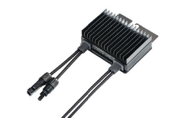
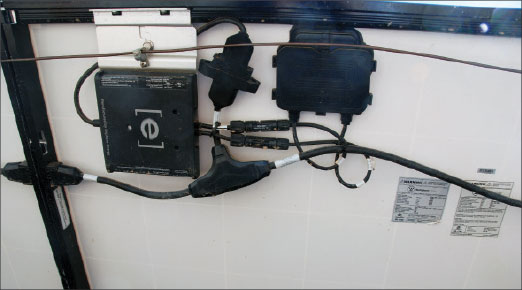
Module level power electronics. Module level power electronics (MLPE) are found within PV module junction boxes and in dc-to-dc converters connected to the module output leads at the module. MLPE decouple (and confuse many) the STC ratings of the PV module and the module output characteristics from the conductors leading to the rest of the string of modules and the PV array and the inverter. The calculations shown above dealing with the PV module characteristics, primarily voltage, current, and power, are no longer applicable to the output of a module with module level power electronics.
MLPE perform several functions which vary from product to product. Some will perform PV rapid shutdown system actions (690.12) using a remote signal. Others will peak-power track the individual module and provide an output that gets as much power from the individual module as possible given the environmental parameters affecting that particular module. Still other module level power electronics will attempt to maximize the output of the module while also maximizing the output of the string containing that module. In nearly all cases the specifications relating to the output parameters of the MLPE will not be comparable to the output of the basic PV module. In nearly all cases, the manufacturer’s instructions provided with the listed/certified module level power electronics device must be followed (110.3 B). There is no possible way that the NEC will be able to address in a general manner all of these numerous varying operating parameters and installation requirements for the numerous systems.
For example, when a certain dc-to-dc converter is connected to an appropriately sized module, the maximum voltage output of this converter is rated at 60 volts. And on the surface, it would appear that at most 10 of these devices could be connected in series to a utility interactive inverter with a dc input rated at a maximum of 600 volts. However, the manufacturer’s literature suggests that optionally 15 of these devices could be connected to that 600-volt inverter because the inverter from that manufacturer communicates with each of the dc-to-dc converters and holds its output under actual operating conditions to a total voltage per string of less than 600 volts. And while this particular dc-to-dc converter is connected to a PV module which has the normal PV module ratings on the label for the module, they are to be essentially ignored and the ratings that apply to the dc-to-dc converter are to be used in determining whether or not it and the PV module have been installed correctly. And of course, when the MLPE is fully contained within the module junction box, the certified/listed PV module with its internal electronics will have a label showing the output characteristics of the combination. The output characteristics of the module level power electronics may, in many cases, no longer follow the classical temperature relationships of the output characteristics of an unprocessed PV module.
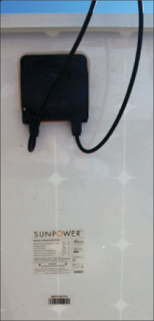
Microinverters and ac PV modules. An ac PV module will have a microinverter mounted to the module frame in relatively close proximity to the module junction box. The ac PV module is certified/listed as a unit and any dc parameters associated with the module, even when they are provided on a label attached to the module, are not to be considered when applying dc code requirements. The microinverter portion of the ac PV module converts the module dc output to alternating current at 120 volts, 208 volts, or 240 volts and this voltage along with the rated output current of the ac PV module is used in determining conductor sizes and the rating of overcurrent and disconnecting devices. The ac PV module is typically connected using a listed trunk cable provided by the manufacturer and the manufacturer’s instructions are to be used in determining how many ac PV modules may be connected to the trunk cable and in what manner.
Microinverters are separate devices connected to a standard dc PV module and they convert the PV module dc output into an ac output very similar to the ac output of an ac PV module. The instructions provided with the microinverter will establish the general size and ratings of the PV module that must be used with a particular microinverter. As before, the dc ratings of the PV module are essentially ignored. In some cases, the microinverter may even be connected to two dc PV modules. Like the ac PV module, a trunk cable is used to connect multiple sets of ac PV modules to the rest of the electrical system, and the voltage rating and current rating of the microinverters connected to the trunk cable will be used to determine other conductor ampacities, and the ratings of overcurrent devices and disconnecting means.
Summary
The calculations relating to the design and installation of dc PV modules to ensure there will be no damage to the connected equipment are relatively straightforward, although they do require knowledge of how the PV module outputs very with ambient conditions. New products entering the marketplace such as dc-to-dc converters, microinverters and ac PV modules, to some extent, will simplify the calculations required to design and install a PV array. The AHJ should be familiar with the older methods a performing these calculations as well as the calculations associated with the newer technologies that, in many cases, can only be found in the product instruction manuals.
Conductor and overcurrent device ratings will be addressed in the next article. Stay tuned for more PV math.
For More Information
The author has retired from the Southwest Technology Development Institute at New Mexico State University, but is devoting about 25% of his time to PV activities to keep involved in writing these “Perspectives on PV’ articles in the IAEI News and to stay active in the NEC and UL Standards development process. Seven to eight-hour presentations are still available on PV and the Code and they cover 2011-2017 NEC requirements. He can be reached at: e-mail: jwiles@nmsu.edu, phone: 575-646-6105.