For certain vital circuits, the 2005 NEC requires that all overcurrent protective devices be selectively coordinated with all supply side overcurrent protective devices in the system. In addition, the definition for selective coordination has been added in Article 100. This commentary includes an overview of the requirements, what selective coordination means, the rationale for the new requirements, system requirements to comply, and the role of designers, contractors and inspectors.
Compliance with these new selective coordination requirements is about the proper choice of overcurrent protection. It is not difficult to choose the proper overcurrent protective device to comply. However, if attention is not given to overcurrent protective device characteristics and proper choices, it is easy to have systems that are not compliant and, thus, systems that do not provide the proper safety of human life.
What Are the New Requirements?
Three new sections in three different articles constitute the changes to the 2005 NEC discussed in this article.
Article 700 Emergency Systems
700.27 Coordination. Emergency system(s) overcurrent devices shall be selectively coordinated with all supply side overcurrent protective devices.
Article 701 Legally Required Standby Systems
701.18. Coordination. Legally required standby system(s) overcurrent devices shall be selectively coordinated with all supply side overcurrent protective devices.
Article 517 Health Care Facilities
517.26 Application of Other Articles. The essential electrical system shall meet the requirements of Article 700, except as amended by Article 517.
Since there is not an amendment on this subject in Article 517, 517.26 requires overcurrent protective devices in essential electrical systems of health care facilities to be selectively coordinated.
The systems covered by these three new sections have normal power sources and alternate power sources in order to maintain power to vital loads. The selective coordination requirement is applicable to all overcurrent protective devices that are part of the conduction path for these systems: that is, from the branch-circuit overcurrent protective devices up through and including all supply-side overcurrent protective devices on both the normal source path and the alternative (emergency) source path. This will be mentioned later in this article. Figures 6 and 7 at the end of the article illustrate this point.
What Is Selective Coordination?
Selective coordination can be defined as isolating an overloaded or faulted circuit from the remainder of the electrical system by having only the nearest upstream overcurrent protective device open.
The following was added to the 2005 NEC Article 100 Definitions: “”Coordination (Selective). Localization of an overcurrent condition to restrict outages to the circuit or equipment affected, accomplished by the choice of overcurrent protective devices and their ratings or settings.””
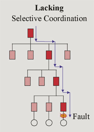
Figure 1. A system with overcurrent protective devices that are not selectively coordinated
One of the better ways to understand selective coordination is to first examine a system that does not provide selective coordination. Figure 1 illustrates a system with overcurrent protective devices that are not selectively coordinated for all possible overcurrents the system can deliver. In this case, a fault occurs on the load side of a branch-circuit overcurrent protective device. The blue arrows represent the fault-current flow from the source to the fault. The branch-circuit overcurrent protective device clears this fault—depicted by the solid red box. In this example, the upstream feeders and main overcurrent protective devices represented by the solid red boxes will also open due to the fault current. The reason is that the overcurrent protective device nearest to the fault is too slow, so the upstream overcurrent protective device(s) also open. However, opening of the other upstream overcurrent protective devices is unnecessary and disruptive. The result is an unnecessary power outage to all the loads with the hashed red and white boxes. This figure 1 system would not be compliant where selective coordination as required.
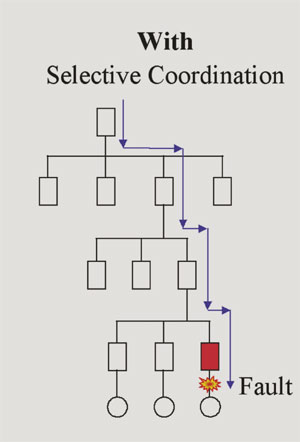
Figure 2. Illustrates a system with overcurrent protective devices that are selectively coordinated for all the possible overcurrents that can occur in the system.
Figure 2 illustrates a system with overcurrent protective devices that are selectively coordinated for all the possible overcurrents that can occur in the system. In this example, the fault occurs on the load side of a branch circuit. The blue arrows represent the fault-current flow from the source to the fault. The branch-circuit overcurrent protective device clears this fault—depicted by the solid red box. However, in this example, no other upstream overcurrent protective devices open. All the feeders and main overcurrent protective devices represented by the boxes with solid white remain in operation. All loads, other than the faulted branch circuit, remain energized and there are no unnecessary load power outages. This is the result of the overcurrent protective devices being properly chosen so that they are selectively coordinated for the range of overcurrents that may occur on this system.
For a system to be selectively coordinated, each overcurrent protective device in each branch circuit, feeder and main must be analyzed for selective coordination with the other overcurrent protective devices in the system. A fault that unnecessarily opens one or more upstream overcurrent protective devices is not selectively coordinated. So if the branch-circuit overcurrent protective device and the next level feeder overcurrent protective device can open on a fault, the system is not selectively coordinated. Also, if the fault occurs on a feeder circuit, to be selectively coordinated, only the overcurrent protective device protecting that feeder circuit shall open; no other upstream overcurrent protective devices shall open. This is similar to the 517.17 requirement for health care facilities where if there are two levels of ground-fault protection, the ground-fault relays on the main and feeders shall be coordinated.
Rationale for the New Requirements
Under Article 700 Emergency Systems
700.1 Scope. …These systems are intended to automatically supply illumination, power, or both to designated areas and equipment in the event of failure of the normal supply or in the event of accident to elements of a system intended to supply, distribute, and control power and illumination essential for safety to human life….
The substantiations for these new proposals center on reliability and continuity of power to vital loads. In an emergency, safety of human life depends on power to each emergency load. Selective coordination of overcurrent protective devices fits well with existing requirements in Articles 700, 701 and 517 that focus on these vital circuits operating as intended when needed and having as much of the system as possible be operational during an emergency. For instance:
700.4 requires initial and periodical testing of the complete emergency system. The system is to be maintained in proper operating condition. This focuses on providing a reliable emergency system that will be operational when called upon for its use.
700.9(B) requires emergency circuits to be physically separated from normal supply circuits. This helps to ensure that emergency circuits will operate when called upon.
700.9(C) requires emergency circuit wiring specifically to be designed and located to minimize failures due to fire, icing or other adverse conditions. This helps to ensure that emergency circuits will operate when called upon.
700.16 requires that for emergency illumination, failure of one component must not result in a condition where a means of egress will be in total darkness.
700.26 has an allowance to not require ground-fault protection for equipment for the alternative source. This demonstrates the preference for system operation in the event of an emergency and the fact that if a ground fault occurs, the whole system should not go down creating an unsafe situation for human life.
The objective of these requirements is safety of human life by ensuring maximum system uptime during emergencies and thus a more reliable emergency system. The exact nature of the threat during an emergency cannot be anticipated. The cause may be due to loss of utility power or it may be due to major physical damage to the building structure caused by fire, earthquake, etc. If some event negatively affects a portion of the emergency system, the criterion is to minimize the impact to the emergency system. Selective coordination of overcurrent protective devices in these vital circuits is another element to minimize the impact of a negative event to the emergency system. Selective coordination is another means to ensure adequate safety to human life in case of an emergency. If there is a fault on one circuit, it is critical to isolate only that portion of the system that must be removed and ensure all other circuits remain powered. Having overcurrent protective devices that are selectively coordinated provides a more reliable emergency system.
The code panel for emergency systems and legally required standby systems made this statement to these proposals:The panel agrees that selective coordination of emergency system overcurrent devices with the supply side overcurrent devices will provide for a more reliable emergency system.
The code panel made a similar statement for legally required standby systems.
System Requirements to Comply
With proper device selection and analysis, it is possible for both fusible systems and circuit breaker systems to be selectively coordinated. However, the proper equipment choice, analysis and interpretation of characteristics are important.
Fusible systems
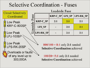
Figure 3. Example of verifying fuse selective coordination
Selective coordination with fuses can be achieved by using the fuse manufacturers’ published fuse selective coordination ratios; a full short-circuit and coordination study is not necessary to verify selective coordination. Figure 3 shows a simple example. The table in figure 3 is an excerpt from one manufacturer’s Fuse Selectivity Ratio Guide. If the system is designed with fuses that maintain fuse type and ampere rating ratios that are equal to or greater than the published ratios, then selective coordination is achieved. There is no need to draw or plot fuse time current curves in order to analyze fuse systems for selective coordination. Just use the ratio guide.
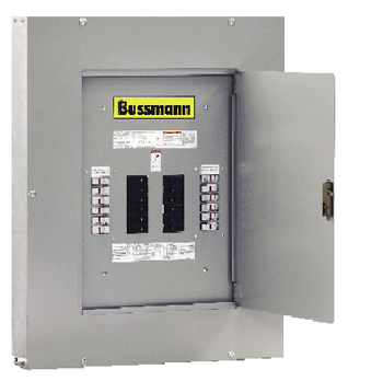
Photo 1. Fusible lighting panelboard (Courtesy of Cooper Bussmann, Inc.)
For a fusible system, in order to achieve selective coordination for the entire system requires fusible branch-circuit lighting panelboards. There has not been an abundance of fused lighting panelboards on the market for many years. However, with these new requirements, fused lighting panelboards for these vital systems are now available. Photo 1 illustrates one manufacturer’s new fusible lighting panelboard.
Circuit breaker systems
Selective coordination with circuit breakers depends on their characteristics and settings, as well as the circuit parameters for the specific application. It is generally difficult to achieve selective coordination with circuit breakers that incorporate instantaneous trip settings. The commonly used molded case circuit breaker has instantaneous trip characteristics that may not be suitable for these critical circuits. A fault on one portion of the circuit can unlatch upstream circuit breakers before the circuit breaker closest to the fault can clear. Typically circuit breakers with short-time delay settings or zone selective interlock features may be necessary. If circuit breakers are to be considered, a full short-circuit current and coordination study must be done with proper analysis and interpretation.
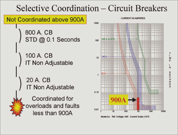
Figure 4. Illustrates a circuit breaker system that is selectively coordinated if the available short-circuit current at the 20-A branch circuit does not exceed 900 A.
Figure 4 illustrates a circuit breaker system that is selectively coordinated if the available short-circuit current at the 20-A branch circuit does not exceed 900 A. For a fault on the 20-A branch circuit less than 900 A, only the 20-A circuit breaker will open. The 100-A and 800-A upstream circuit breakers will not open under this circumstance. Also, if a fault occurs on the 100-A feeder circuit, only the 100-A circuit breaker will open since the 800-A circuit breaker has a short time delay. So in this case, the 100-A and 800-A circuit breakers are selectively coordinated.
In Figure 4, if the available short-circuit current does exceed 900 A at the 20-A branch circuit, then the upstream feeder circuit breaker may open for a fault on the 20-A branch circuit; this is not a selectively coordinated system. A short-circuit current study and coordination study can determine whether this type circuit breaker design is selectively coordinated for the specific system parameters. If this type system is found suitable today, future system changes that
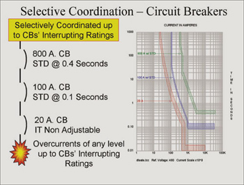
Figure 5. Illustrates a circuit breaker system that is selectively coordinated for the full range of overcurrents up to the interrupting rating of each respective circuit breaker
increase the available short-circuit current may negate their suitability.
Figure 5 illustrates a circuit breaker system that is selectively coordinated for the full range of overcurrents up to the interrupting rating of each respective circuit breaker. The branch-circuit breaker is a standard 20-A molded case circuit breaker (with instantaneous trip) and the feeder and main circuit breakers have short-time delay settings with no instantaneous trip settings.
Figures 6 and 7 at the end of this article illustrate selective coordination and non-coordination through the normal power supply and the emergency power source.
The Cooper Bussmann SPD Selecting Protective Devices publication (download fromwww.bussmann.com) has an in-depth discussion on selective coordination analysis with published fuse selectivity ratios, some simple rules for evaluating coordination of instantaneous trip circuit breakers, and an illustration of short-time delay circuit breakers.
New Requirement Compliance
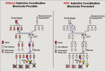
Figure 6. Analysis of selective coordination for emergency system from the normal source of power
Achieving overcurrent protective device selective coordination for a system requires the proper engineering, specification and installation of the required devices; and, in addition, knowledgeable plan review and inspection are required to ensure compliance. The designer, contractor, and plan review/inspector each has his or her role in compliance to selective coordination in order to ensure safety to human life.
Role of designers
For these vital systems, the designer must select, specify, and document overcurrent protective devices that achieve selective coordination for the full range of possible overcurrents and for faults at all possible points in the system (faults can occur in the branch circuits, sub-feeders, and feeders).
For fusible systems, it is a matter of selecting the fuse types and ampere ratings that adhere to the manufacturer’s selectivity ratio guide. This ensures selective coordination for overcurrents up to the interrupting rating of the fuses, which is typically 200,000 A or 300,000 A. The plan specifications must detail the specific type fuses and ampere ratings that are designed into the system to achieve selective coordination for the system. This is important so that the contractor quotes and installs the proper type and ampere rating fuses to achieve selective coordination.
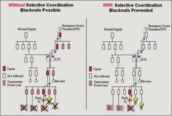
Figure 7. Analysis of selective coordination for emergency system from the alternative source of power
For circuit breaker systems, a short-circuit current study and coordination study are needed that detail the system available short-circuit currents, the specified circuit breaker types and settings, and analysis that selective coordination is achieved for the full range of available overcurrents. It is important that the plan specifications detail the type circuit breakers and specific circuit breaker settings to achieve selective coordination. This information is necessary so that the contractor quotes, installs and sets the circuit breakers as designed.
Role of contractors
Contractors must install the system as designed to ensure selective coordination for the system. If a fusible system, install the fuse types and ampere ratings as called for in the design. If a circuit breaker system, install the circuit breaker types with the specified settings.
If the contractor opts to suggest a value engineering option for these vital systems, it is critical that the engineer evaluates and approves of any changes. For instance, value engineering with overcurrent protective devices that are series rated combinations may reduce the cost, but series rated combinations may be difficult to selectively coordinate. Hence, extra analysis may be required if series rated combinations are considered for use in emergency circuits, legally required standby circuits, and essential circuits in health care facilities.
Role of plan review/inspectors
During the plan review process, the engineer must provide the substantiation in the form of documentation that his design achieves selective coordination for these vital circuits. The plan reviewer should not have to prove or disprove that selective coordination is achieved. The engineer’s documentation should be clear enough to demonstrate that the design work included the proper selective coordination analysis and that the plans and specifications clearly articulate the required details on type of overcurrent protective devices, ampere ratings, and settings (if circuit breakers). The engineer’s documentation should clearly state that the plans specify overcurrent protective devices that achieve selective coordination for these vital systems.
During the inspection process, prior to energization, the field inspection should include verifying that the overcurrent protective devices have been installed as specified. If circuit breakers are used, the settings should be verified as per plan.
Summary
These new requirements for selective coordination of overcurrent protective devices in emergency systems, legally required standby systems, and health care facility essential electrical systems provide better system reliability for the safety of human life. Selective coordination can be defined as isolating an overloaded or faulted circuit from the remainder of the electrical system by having only the nearest upstream overcurrent protective device open. It is possible for both fusible systems and circuit breaker systems to be selectively coordinated with proper selection and analysis. Achieving the proper overcurrent protective device selective coordination for a system requires proper engineering analysis, specification and installation of the required devices. During the plan review process, it is the design engineer’s responsibility to provide documentation that verifies the overcurrent devices are selectively coordinated for the full range of overcurrents that can occur in the system. And the site inspection should verify the overcurrent protective devices are installed as specified to achieve selective coordination.