The Basics of Selective Coordination
Selective coordination is achieved when overcurrent protective devices are chosen such that whenever an overcurrent occurs only the nearest upstream overcurrent protective device (OCPD) opens to interrupt the overcurrent. In figure 1, this means if a fault occurs on the load-side of OCPD 1 (100 A), only that device opens. Neither OCPD 2 (200 A) nor OCPD 3 (800 A) opens.
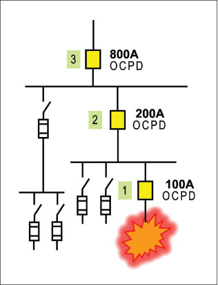
Figure 1. One-line diagram shows fault on branch circuit 1.
Selective coordination for the full range of overcurrents possible in a system is anNEC®requirement for certain systems (Sections 700.27, 701.18, 708.54, 620.62, and 517.26) where continuity of power for loads is vital for life safety. A short-circuit current analysis (study) is usually considered part of the required documentation and its purpose is to provide the maximum available short-circuit currents throughout the distribution system. However, for a few selective coordination analysis methods, a short-circuit current study is not necessary. This fact will be mentioned when those methods are covered in this article.
When a short-circuit study is performed, the available short-circuit current is determined at the line-side terminals of each overcurrent protective device. This information is also necessary to verify the OCPDs have adequate interrupting rating (IR) to comply withNEC110.9 and that the equipment has adequate short-circuit current ratings (SCCR) to comply withNEC110.10, 409.101, 440.4(B), and 670.3(A). This concept is depicted in figure 2. The X1, X2and X3represent the available short-circuit current at the line-side terminals of OCPD 1, OCPD 2, and OCPD 3, respectively. The values of 15,000 A, 25,000 A, and 30,000 A for X1, X2and X3, respectively, were selected for illustrative purposes only. These values are in RMS symmetrical amperes.
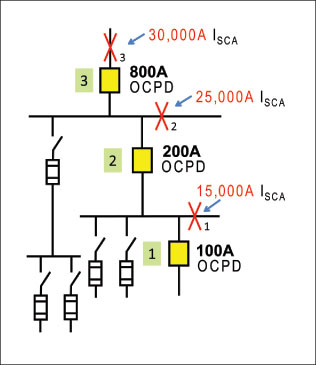
Figure 2: One-line diagram showing available short-circuit currents. ISCA represents short-circuit current available.
A typical selective coordination requirement:
NEC700.27 Coordination.
“Emergencysystem(s) overcurrent devices shall be selectively coordinated with all supply side overcurrent protective devices.” (with two exceptions)”
Reading the specific language of the requirement means: OCPD 1 must selectively coordinate with OCPD 2andOCPD 3 for all overcurrents up to the maximum available at X1(15,000 A). OCPD 2 must selectively coordinate with OCPD 3 for all overcurrents up to the maximum available at X2(25,000 A).
Selective Coordination Utilizing Fuses
The basics in evaluating circuits for selective coordination using fuses are relatively simple. There are two approaches:
a. Fuse manufacturer’s published selectivity ampere rating ratios.
b. Interpret time-current curves.
Example a: Fuse Selectivity Ampere Rating Ratios
The simplest and preferred method for fuses is to adhere to the fuse manufacturer’s published selectivity ampere rating ratios. No need to interpret time-current curves. Valid for any overcurrents up to 200 kA (200,000 amps) or fuse interrupting rating, whichever is less. Today most current-limiting, branch-circuit fuses have at least a 200 kA interrupting rating. With this method, the fuses must be of the same manufacturer. These fuse amp ratio tables are based on testing by each fuse manufacturer and there is no published data for mixing fuses of different manufacturers. The selectivity amp rating ratios vary by the type of fuses. One fuse type may require only a 2:1 amp rating ratio between a line-side fuse and a load-side fuse. If different types of fuses from the same manufacturer are used line-side and load-side, then the ratio might be different, such as 3:1, 4:1, or 8:1. As with any method or table, be sure to read any applicable notes or footnotes.
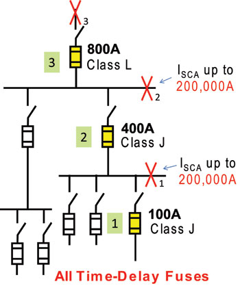
Figure 3: Example to Evaluate Fuse Selective Coordination
Each fuse manufacturer publishes a selectivity ratio table specific to only their brands. Table 1 is for illustrative purposes and should not be used in actual studies.
Analysis for Figure 3 using Table 1
Investigate the circuit for fuses 1, 2, and 3 in figure 3 using the Selectivity Amp Rating Ratio Table method.
1. Check fuse 1 with fuse 2
• For the actual fuses, the line-side to load-side amp rating ratio is 400 A:100 A = 4:1
• Both fuse 1 and fuse 2 are Class J time-delay and Table 1 shows a ratio of 2:1 or greater is necessary.
• Therefore since the actual amp rating ratio for fuse 1 and fuse 2 (4:1) is equal or greater than 2:1 (Table 1), fuse 1 will selectively coordinate with fuse 2 for any overcurrent up to 200 kA.
2. Check fuse 1 with fuse 3
• Actual amp ratio is 800 A:100 A = 8:1
• 2:1 or greater is necessary (Table 1).
• Fuse 1 selectively coordinates with fuse 3 up to 200 kA.
3. Check fuse 2 with fuse 3
• Actual amp rating ratio is 800 A:400 A = 2:1
• 2:1 or greater is necessary (Table 1).
• Fuse 2 will selectively coordinate with fuse 3 for any overcurrent up to 200 kA.
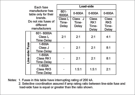
Table 1: Fuse Selectivity Amp Rating Ratio Guide
Conclusion: This circuit path is selectively coordinated for any overcurrent up to 200 kA; therefore, X1and X2could be any value of available short-circuit currents up to 200 kA. Using this method, there is no need to do a short-circuit current study if a quick assessment shows the short-circuit currents in the system will be 200 kA or less.
Example b: Fuse Selectivity Time-Current Curves
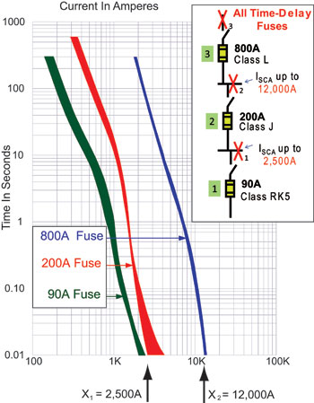
Figure 4: Interpreting time-current curve method
Use this method only for the portion of the curve that is visible on the time-current graph. The typical standard industry time-current curve has a vertical time axis from 0.01 seconds up to 300 seconds or 1000 seconds. However, fuses when operating in their current-limiting range, clear in less than 0.01 seconds. Depending on the fuse type, amp rating, and available fault current, the clearing time can be less than 0.01 sec. (Time-current curves typically are not published for times less than 0.01 seconds.) It is simpler and more comprehensive to use the FuseSelectivity Ampere Rating Ratios method illustrated previously rather than interpreting time-current curves.
In this example, use the fuse time-current curves in figure 4 to analyze selective coordination for the circuit path with the three fuses shown. Examining figure 4, there is no overlap of the fuses’ time-current curves. However, this does not mean that the fuses are selectively coordinated for the full range of overcurrents up to their interrupting rating. What can be interpreted from figure 4 is that the 90-A Class RK5 time-delay fuse is coordinated with the 200-A Class J time-delay fuse up to 2500 A and is coordinated with the 800-A Class L time-delay fuse up to 12,000 A. Also, the 200-A Class J time-delay fuse is coordinated with the 800-A Class L fuse up to 12,000 A.
Conclusion: If this specific system has available short-circuit currents for X1of 2,500 A or less and X2of 12,000 A or less; then, this circuit is selectively coordinated.
Note: The conclusion does not mean these fuses are not selectively coordinated for higher fault currents; it just means we cannot draw that conclusion by interpreting the time-current curve method. To illustrate this point, use the fuse selectivity amp rating ratio method and Table 1 to check figure 4 for fault currents up to 200 kA for X1and X2. The ratio required by Table 1 for Class J time-delay fuse line-side of a load-side Class K5 time-delay fuse is 8:1. In the circuit for figure 4, the actual fuse ratio is 200 A:90 A = 2.2:1. So, using the ratio method, these two fuses would not be selectively coordinated up to 200 kA. However, figure 4 does show these two fuses are selectively coordinated up to 2,500 A. Now investigate the 800-A and 200-A fuses using the ratio method. The ratio required by Table 1 for Class L time-delay fuse line-side of a load-side Class J time-delay fuse is 2:1. In the circuit for figure 4, the actual fuse ratio is 800 A:200 A = 4:1. So, using the ratio method, these two fuses are selectively coordinated up to 200 kA. This is a good example of why it is quicker and simpler to just use the fuse selectivity ampere ratio method rather than plotting the time-current curves and interpreting.
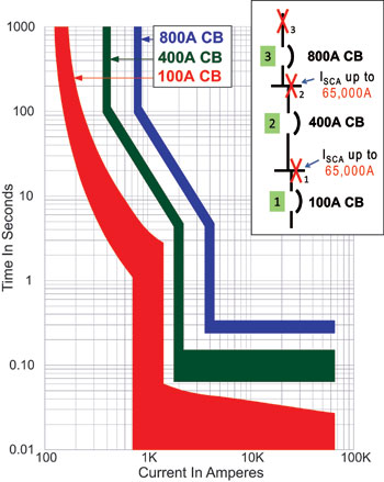
Figure 5: Circuit breaker time-current curves do not cross and therefore the circuit is selectively coordinated for available short-circuit currents up to the CB interrupting ratings.
Selective Coordination Basics for Circuit Breakers
The basics in evaluating circuits for selective coordination using circuit breakers (CBs) are also relatively simple. There are three approaches.
a. If the clearing time of all the CBs is greater than 0.01 seconds for the line-side available short-circuit current, the CB time-current curves cannot cross.
b. If the CB time-current curves cross, the available short-circuit current at the point of intersection is interpreted as the maximum short-circuit current to which selective coordination can be achieved. There is an exception if CB manufacturers’ Selectivity Tables provide data verifying two specific CBs selectively coordinate to a higher short-circuit current level.
c. If clearing time of the CB is less than 0.01 seconds, then data is needed from the circuit breaker manufacturer’s table method discussed inb.
The following will give an example for methodsaandb.
Example a: CB Curves Do Not Cross
The easiest CB systems to interpret are those where the CB time-current curves do not cross. To achieve this “no overlap” situation, it normally requires the use of feeder and main CBs with short-time delay settings and no instantaneous trip (or instantaneous override). The branch circuit CB can have an instantaneous trip. Figure 5 illustrates where such a system is selectively coordinated for any overcurrent up to the interrupting rating of the CBs, which is 65 kA in this example. With this method, CBs of different manufacturers can be mixed.
Example b: CB Curves Cross
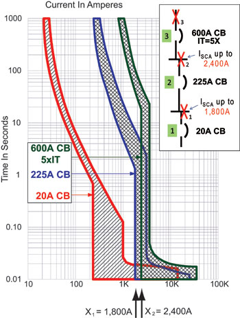
Figure 6. Selectively coordinated for available short-circuit currents up to where circuit breakers cross. 600-A CB instantaneous trip set at 5 times.
If the CB time-current curves cross, then there are two approaches to evaluate selective coordination. The first approach is to interpret the time-current curves such that two CBs are selectively coordinated up to the available short-circuit current where the curves cross. The analysis of figure 6 is as follows:
• 20-A CB is selectively coordinated with the 225-A CB for available short-circuit currents up to 1800 A and with the 600-A CB for available short-circuit currents up to 2400 A.
• 225-A CB is selectively coordinated with the 600-A CB for available short-circuit currents up to 2400 A.
Conclusion: If the available short-circuit current at X1is less than 1800 A and at X2less than 2400 A, this circuit is selectively coordinated. If the available short-circuit current at X1is greater than 1800 A, or at X2, greater than 2400 A, this circuit is not selectively coordinated.
With this method, circuit breakers of different manufacturers can be mixed and evaluated for selective coordination. If the instantaneous trip of the circuit breaker is adjustable, then by setting the adjustment higher or lower one can change the available short-circuit current at which the CBs selectively coordinate. In the figure 6 example, the 225-A CB is a fixed instantaneous trip, so it cannot be changed. However, the 600-A CB has an adjustable instantaneous trip range from 5 to 10 times. In the figure 6 example, it was set on 5 times. If the 600-A CB instead had its instantaneous trip set at 10 times, then the analysis would be as follows using figure 7:
• The 20-A CB is selectively coordinated with the 225-A CB for available short-circuit currents up to 1800 A and with the 600-A CB for available short-circuit currents up to 5200 A.
• The 225-A CB is selectively coordinated with the 600-A CB for available short-circuit currents up to 5200 A.
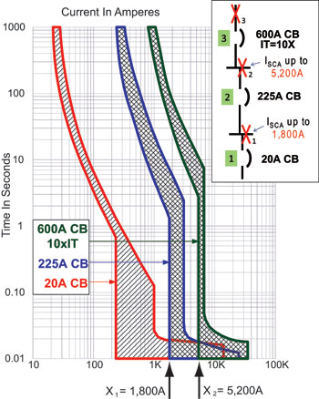
Conclusion:
If the available short-circuit current at X1is less than 1800 A and at X2less than 5200 A, this circuit is selectively coordinated. If the available short-circuit current X1is greater than 1800 A, or at X2, greater than 5200 A, this circuit is not selectively coordinated.
Example: CB Selective Coordination Tables
The previous method of interpreting CB time-current curves has been an industry standard for decades. However, with the advent of theNECrequiring selective coordination for some systems where life safety is vital, manufacturers have developed CB to CB selective coordination tables. These tables typically are based on testing and analysis, and the presentation format varies for each manufacturer. Each CB manufacturer has tables for their CBs and the data is specific to type and amp rating of each circuit breaker. The tables assume CB instantaneous trips are set on the highest settings. Table 2 is a fictitious CB to CB selective coordination table. The format is line-side CB across the top and load-side CB down the left side. Using Table 2, the following is an example for the CBs in figure 8.
• Type B 20-A CB is selectively coordinated with the Type F 225-A CB for available short-circuit currents up to 2200 A and with the Type G 600-A CB for available short-circuit currents up to 15,000 A.
• Type F 225-A CB is selectively coordinated with the Type G 600-A CB for available short-circuit currents up to 12,000 A.
Conclusion:If the available short-circuit current at X1is less than 2200 A and at X2less than 12,000 A, this circuit is selectively coordinated. If the available short-circuit current at X1is greater than 2200 A or at X2greater than 12,000 A, this circuit is not selectively coordinated.
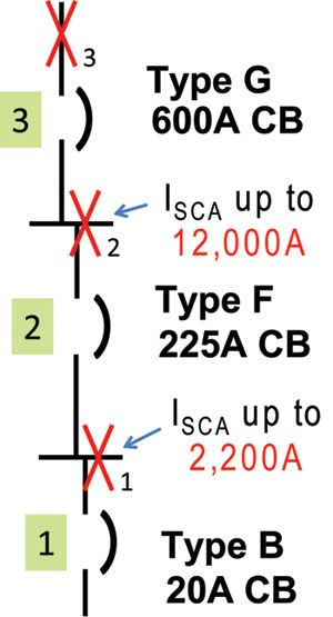
Figure 8. CB selective coordination table method
Note: Selective coordination tables are CB manufacturer specific and even specific for the type or style CB. The short-circuit current values at which line-side and load-side CBs selectively coordinate vary widely between the manufacturers and even for different CB types of the same manufacturer. For instance, a manufacturer may have numerous types of 600-A frame molded-case CBs, as well as insulated-case CBs and low-voltage power CBs in 600 A ratings. Therefore, if the CB table method is utilized, it is important to ensure that the selective coordination submittal be very specific on the CB manufacturer, CB type, CB frame/amp rating. It is suggested that the submitter include the manufacturer’s selective coordination tables as part of the submittal documentation.
System with Mixture of Fuses and Circuit Breakers
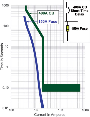
If an upstream CB has only a short-time delay trip and no instantaneous trip, then selective coordination is assured if the fuse curve and CB curve do not cross (figure 9).
If the upstream CB has an instantaneous trip, it is not a simple matter to determine if a downstream fuse will be selectively coordinated. Even if the plot of the time-current curves for a downstream fuse and an upstream circuit breaker with instantaneous trip show that the curves do not cross, selective coordination may not be possible beyond a certain fault current. This is in the fault region where the fuse is clearing in less than 0.01 seconds. This is because the fuse may not clear the fault prior to unlatching of the upstream circuit breaker. The sure way to determine whether these two devices will coordinate is to test the devices together. Figure 10 illustrates that the 200-A fuse is selectively coordinated up to 3500 A short-circuit current; beyond that fault current, it is not certain unless there is test data.
If a fuse is upstream and a CB is downstream, at some point the fuse time-current characteristic crosses the CB time-current characteristic. For short-circuit currents at that cross-over point and higher, the upstream fuse is not coordinated with the downstream CB. Figure 11 shows a 200-A fuse with downstream 20-A CB. Selective coordination is possible up to 2200 A, but beyond that point the fuse characteristic crosses the CB curve. So beyond 2200 A, the 20-A CB is considered not to be selectively coordinated with the 200-A fuse.
Simple Suggestions to Implement Enforcement
Quick Short-Cut Checks
It is always good to have quick short-cuts to spot check on any process and there are some easy approximate short-cuts for selective coordination. If the system is fusible, simply use the fuse manufacturer’s selectivity ratio table.
If the system consists of circuit breakers with instantaneous trips, such as molded case CBs, then there is a simple method to check whether selective coordination is achieved. For each CB, simply multiply the instantaneous trip setting by the CB’s amp rating. The resulting product is the approximate short-circuit current at which a CB enters its instantaneous trip region. This simple method is a practical, quick test in assessing if a system is selectively coordinated. There may be other means to determine higher values of fault current where CBs selectively coordinate (such as manufacturers’ tables). This quick check is approximate in that you may have to assume an IT setting. The following illustrates this simple method without considering manufacturing tolerances.
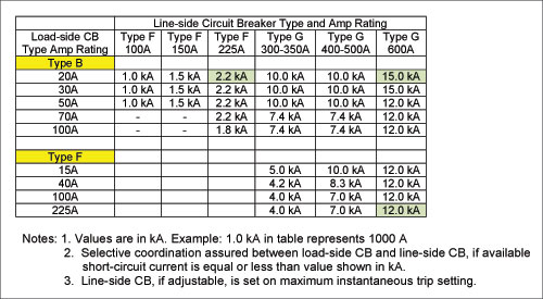
Table 2. Circuit breaker selective coordination table
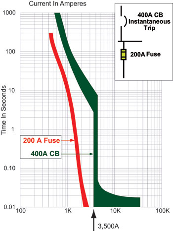
Figure 10. 200-A fuse and upstream 400-A CB with instantaneous trip are selectively coordinated up to 3500 A.
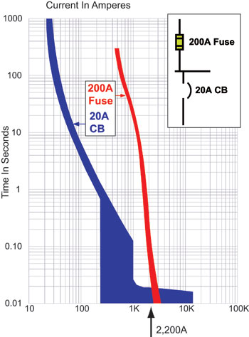
Figure 11. 20-A CB selectively coordinates with 200-A fuse up to 2200 A.
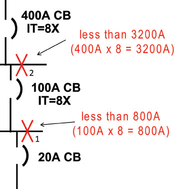
Figure 12. Illustrates simple method to check CB coordination without considering the manufacturing tolerances
Using figure 12, let’s assume an emergency circuit has three CBs: 400 A, 100 A, and 20 A.
a. Assume the 100-A CB has its instantaneous trip (IT) set at 8 times (8X) its amp rating. Therefore, for fault currents above 800 amps (100 A x 8 = 800 A), the 100-A CB will unlatch in its instantaneous trip region, thereby opening.
b. Assume the 400-A CB has its instantaneous trip set at 8X its amp rating. Therefore, for fault currents above 3200 amps (400 A x 8 = 3200 A), the 400-A circuit breaker unlatches in its instantaneous trip region, thereby opening.
Conclusion:The 20-A CB will selectively coordinate with the 100-A CB if X1is less than 800 A. The 100-A CB will selectively coordinate with the 400-A CB if X2is less than 3200 A.
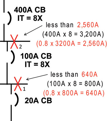
Figure 13. Illustrates simple method to check CB coordination including considering the IT pickup manufacturing tolerance
For simplicity, the previous example did not include the manufacturing tolerances permitted for instantaneous trip pickup. UL 489 for molded-case CBs permits IT pickup tolerances of -20% and +30% of the instantaneous trip setting. Now let’s review the previous stepsaandband then do the additional stepcbelow, which factors in the IT pickup tolerance; figure 13 provides the one-line:
c. If the instantaneous trip pick-up negative tolerance is factored in, then take 80% of the results in previous steps a and b (multiply the results by 0.8). The 100-A CB will open at 100 A x 8 x 0.8 = 640 A and the 400-A CB will open at 400 A x 8 x 0.8 = 2560 A.
Conclusion:If the available short-circuit current is less than 640 A (0.8 times 800 A) and 2560 A (0.8 times 3200) for X1and X2, respectively, selective coordination is achieved. If the fault current is greater for either X1or X2, selective coordination is not achieved.
Additional Resources
• Two IAEI News articles found in the IAEI News magazine online www.iaei.org/magazine/:
“Overcurrent Protection Basics, Part I,”March-April 2007, author Tim Crnko: provides some basics on reading time-current curves, circuit breaker and fuse operation, and understanding time-current curves for each.
“Selective Coordination – Responsibilities of the AHJ,” November-December 2007, author Mark Hilbert: provides information on what is selective coordination, the requirements, and AHJ role.
• “Keep The Power On for Vital Loads,”NEC Digest, December, 2007, author Evangelos Stoyas: provides insight why we have mandatory selective coordination and important aspects of the requirement. Available to NFPA members at nfpa.org or from www.cooperbussmann.com/2/SelectiveCoordination.html
• NECA 700(2010)–Installing Overcurrent Protection to Achieve Selective Coordination at neca-neis.org. This newly developed standard has in-depth information on the “how to” of selective coordination.• Circuit breaker companies have several tools including CB to CB selective coordination tables: the publications are Eaton 1A01200002E, SQD 0100DB0501R3/06, and GE DET-537B.
• Cooper Bussmann has several tools in their2008 SPD(Selecting Protective Devices) publication including sections on selective coordination for fuses or circuit breakers, why selective coordination is mandatory, AHJ check list, simple point-to-point short-circuit current calculation method, and checking CB coordination by simplified method without time-current curves. In addition, a free simple short-circuit current calculator program can be downloaded. Go to www.cooperbussmann.com/spd.