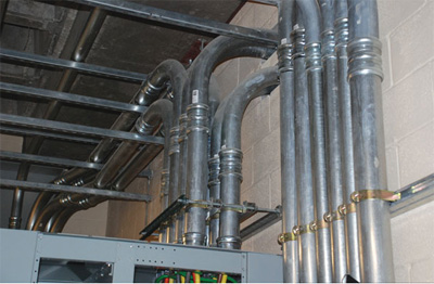
 For most electricians, the proper use of fittings is elementary. Fittings themselves are pretty straightforward in their use. ReferencingDefinitionsin theNational Electrical Codeunder the entry:Fittings, we are informed that a fitting is “an accessory such as a locknut, bushing, or other part of a wiring system that it is intended primarily to perform a mechanical rather than an electrical function.” From experience, we know that fittings are straps, hangers, couplings and connectors which connect (or couple) a raceway to itself, a box, device, enclosure, or similar electrical apparatus — pretty simple. This simplicity becomes a matter of thought and caution when coupling different types of raceways together, especially, when compounded with the issues of wet locations.
In dry locations, transitioning between raceways has been historically accomplished by a box, conduit body, or through the use of a steel coupling. The steel coupling transition is probably the most common. In this application, two connectors are used in conjunction with a steel coupling to form a “from–to” (from this to that). While this type of installation is accepted by most AHJs, it has several inherent weaknesses that should be understood and addressed. The most obvious weakness of this fitting assembly lies in its lack of a listing. Without a listing, the fitting violates the NEC and must rely on AHJ acceptance.
The “from–to” fitting assembly is a violation of the NEC because of section 300.15 which states: a fitting must be used only in the application it is listed: “fittings … shall be used only with the specific wiring methods for which they are designed and listed.” The MC connector and the EMT connector are both listed for use with MC and EMT, but the steel coupling is only intended for use as a coupling for rigid metal conduit, and not as a coupling for two different connectors. Therefore, the “from–to” in photo 1 is not a listed assembly. Many jurisdictions allow this type of installation, relying on AHJ acceptance, but should only do so with an understanding of the inherent weaknesses of the “from–to” assembly.
In photo 1, we see a dry locations conversion. This “from–to” assembly uses a ¾″ EMT set screw connector, a steel coupling; a ¾″ to ½″ reducing bushing, and a duplex mc connector to assemble a transition between ¾″ EMT and two 3/8″ metal-clad cables (MC). When referring back to the definition of a fitting, we understand that a fitting must meet two criteria. First, it must perform its mechanical duties in terms of connecting the raceways or cables together. Second, a fitting must also provide a low-impedance path for the continuity of the raceway, or its electrical function. Any fitting, used with metallic raceways, must not offer impediment to the flow of current. When constructing or evaluating any transition between raceways, these two factors can provide the guidelines for their acceptance. Does the transition offer good mechanical strength? Will the fitting or assembly impede the flow of current?
While the dry location transition in photo 1 likely offers good mechanical strength, it might not meet the second criteria of a fitting: its electrical function. This is where a “from–to” becomes problematic as the connection relies on the tightening of the duplex MC connector against the steel coupling. In this case, the shoulders of the MC connector are in contact with the steel coupling in order to make the assembly tight. These shoulders and the threads (which also include the addition of a reducing bushing) must work together to create the system bonding path and offer little or no impedance to the flow of current. If the fitting is slightly corroded, the two small points of contact on the MC connector will provide the primary equipment bonding path and this “from–to’s” electrical function will likely be less than adequate. If installed loosely or if corroded, the fitting is in violation of the National Electrical Code as it does not perform both of its intended functions. While the AHJ may still find their use acceptable, this acceptance should be dependent upon a tight and corrosion-free installation until an acceptable listed alternative becomes readily available.
When transitioning between conduit systems, it is possible to use code-compliant products that are listed expressly for coupling different raceways.The combination coupling or the transition fitting is available for most of the applications in the field. The conversion of EMT to Rigid, EMT to FMC, Rigid to Liquidtight or any combination thereof can be accomplished using UL listed products. As an example of these products: a Bridgeport Fittings 4361-DC (photo 2) is a listed fitting, specifically designed for transitions between EMT and Liquidtight. The 4361-DC is also suitable for use in wet locations.
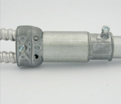
Photo 1. A dry locations conversion which likely offers good mechanical strength; however, it might not provide good electrical function.
Unfortunately, listed transition fittings are seldom offered above the 1 inch trade size. As a solution for larger trade sizes, the electrician has a few options. The first, and most obvious, option would be to install a “from–to” using the steel coupling transition between two connectors. This should not be considered an option for wet locations as the internal threads of the steel coupling are prone to corrosion. A more electrically viable option is for the electrician to use threaded fittings, joined together by a junction box or enclosure. This option can be costly and dependent on the space available. The third option is to use two connectors installed in a conduit body; in particular, a “C” style conduit body. By threading two different raceway connectors into either end, the installer is afforded an opportunity to transition, as well as access to the conductors. Using a conduit body to transition between two different raceways requires the consideration of several variables. First, a proper fit must be insured, so that that the mechanical and electrical functionality is maintained. Second, this transition method requires AHJ acceptance as this fitting assembly has risks related to listing requirements which are similar to the “from–to.”
The primary issue with the conduit body transition is thread compatibility. It is important to select connectors based on the thread type of the conduit body. There are several important variables which should be understood when installing a conduit body transition. These variables are also pertinent when installing any fitting into a hub, be it a conduit body, motor attachment point, or service-entrance equipment.
There are two common types of threads used in the manufacture of fittings:
NPT or National Pipe Standard Tapered Thread. In this configuration the threads gradually taper at a very slight angle. This is the thread type which is applied to rigid conduit during field treading and can be found on many types of liquidtight fittings (Figure 1).
Straight Threads or NPSM (Pipe Straight Mechanical Fit): Straight thread type is manufactured to one dimension only. NPSM is essentially straight style threading with a very slight modification for ease of fit. Commonly referred to as a modified straight thread, this is the most common type of threading found on fittings (Figure 1).

Figure 1. A comparison of NPT (tapered) and NPSM (straight) threads
The two main types of threads are also manufactured with a wide degree of variability and tolerance. It is this variability that will affect how the fittings fit. These variables also add another layer of complication when installing fittings into hubs and it also illustrates the issue at hand: a lack of standardization.
There are general guidelines which manufacturers follow: Straight or NPSM threads are usually utilized on fittings designed for dry location use with a locknut. Tapered threads are primarily utilized on hubs which are designed for use with rigid conduit. They can be found on EMT fittings for use in wet locations (commonly referred to as “raintight”) and metallic liquidtight connectors. This guideline isn’t always the rule, especially, when fittings are used in both wet and dry locations.
By examining one of the most common wet location raceway conversions, several important installation and inspection issues become evident. The assembly in photo 3 is made up of an EMT connector, a liquidtight connector and a steel coupling. In this instance, we know that the steel coupling has straight threads. This will allow for a reasonably good mechanical connection, but this “from–to” might prove problematic over time as the fittings age and corrode. Steel couplings offer very little corrosion protection, especially on the internal threads. Either way, we will have a good mechanical connection, but our electrical connection could be impeded by corrosion. To what degree this ability is hindered, we would have no way of truly knowing, but it is fair to assume that the threads inside of the steel coupling would experience oxidation rather quickly, inhibiting the continuity of the raceway, and, again, we have a violation of the NEC with an increase in raceway impedance.
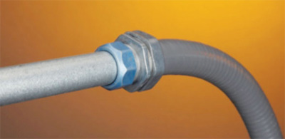
Photo 2. Bridgeport fittings 4361-DC
Had the installer used a wet location rated “C” style conduit body (see photo 4), the connection would have much greater wet location integrity. Unfortunately, using a conduit body as a transition between raceways offers several hurdles that must be overcome in order to insure that a mechanically strong, low-impedance connection is made. Dry location fittings are often designed with straight or NPSM threads and are considered to be listed for use with locknuts only. On the other hand, so are FMC connectors which have an expectation of use on motor termination housings which are usually constructed with hubs. The same logic applies to wet location fittings. There is also an expectation that liquidtight and EMT connectors can be used with conduit bodies and have been for many years. The issue of fit has created some confusion. The problem with conduit bodies occurs when we mix an NPSM fitting with an NPT conduit body. The two will not thread together correctly. This is the crux of the problem: straight threads into tapered bodies.
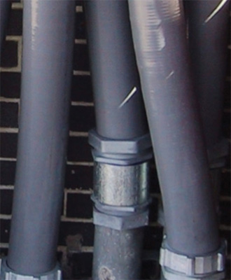
Photo 3. This assembly is made up of an EMT connector, a liquidtight connector and a steel coupling with straight threads, which allows for a reasonably good mechanical connection. Over time, however, this “from–to” might prove problematic as the fittings age and corrode.
The transition in photo 4 offers a good mechanical connection and offers good corrosion protection. The conduit body and the fittings are all NPT. While this connection is more than adequate for the application, it may not be listed and would likely have to rely on AHJ acceptance. Installing an EMT or liquidtight connector into a conduit body, motor hub, or hub of service-entrance equipment may not be a listed application. Do we violate the listing of the product and 300.15 when using this practice? Let’s start with UL’s interpretation.
In June 2010, Mark Ode, a staff engineer at UL, commented on the matter (“Fittings into Hubs: Good for grounding or not?” Electrical Contractor Magazine, p 119). Mark Ode’s interpretation of the issue is that all hubs are intended for use with rigid conduit only. His article focused on the use of EMT connectors and the hub, or boss in a conduit body. Mr. Ode also discussed the specific hazards associated with the practice and identified the thread style as the main obstacle to the practice. His article concluded that EMT fittings should not be used with conduit bodies and that mixing of thread types leads to improper fit, and added raceway impedance. He is absolutely correct that mixing threads can lead to a compromised connection. Mr. Ode’s assessment is that rigid conduit is the listed application for most conduit bodies and that connectors for EMT are not typically listed for use with hubs or bosses, but there are two other important factors that must also be addressed.
Flexible metallic conduit connectors and liquidtight connectors offer the same hurdles as EMT connectors and there is an expectation that they are for use with hubs.
Conduit bodies are just one of many applications where we encounter hubs. Motors, service entrances, weatherproof boxes and exterior lighting packs offer the same hurdles as conduit bodies.
Mark Ode’ “Fittings into Hubs” article addresses these issues, but his assertion that EMT fittings into hubs of conduit bodies should never be done, should be tempered with the qualifier: unless a qualified electrician and AHJ deem it acceptable. Electricians can use their knowledge as craftsmen to determine if an application will provide both: good mechanical strength, and a low impedance path to the flow of current. Using fittings in conduit bodies or hubs can be permitted provided the thread types are not to be mixed unless a good fit is the result. Many conduit bodies offer a high tolerance NPSM thread that will engage properly with both an NPSM (straight) and NPT (tapered) thread.
As an installation requirement to this listing issue with both the conduit body and the steel coupling, we can make some assumptions based on what we know:
In dry locations, corrosion is not usually a factor, so the steel coupling shouldn’t corrode, but installers should insure that the fitting is installed correctly and that it is more than hand tight. Looseness should not be accepted. A fitting should not be able to be unscrewed by hand.
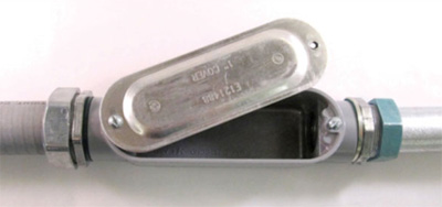
Photo 4. A wet location rated “C” style conduit body offers much greater wet-location integrity, but using a conduit body as a transition between raceways also offers hurdles to a strong, low-impedance connection.
In wet locations, rigid conduit is manufactured with a tapered thread and a tapered thread is also applied during field threading. This thread configuration provides adequate continuity for a safe raceway in terms of mechanical strength and electrical continuity when installed into a straight thread steel coupling. The same can be said for conduit bodies using NPSM (straight) and NPT (tapered) hubs that are connected to a threaded connector whatever the configuration is, as long as a proper fit is ensured. Raintight or liquidtight connectors must be installed with a sealing washer as it is a part of the listed assembly, so the sealing washer will have to remain on any connection.
The easiest way to see whether a fitting engages a hub properly, or not, is to dry fit the assembly first. This will ensure that during the installation, the final product will offer both a low-impedance connection and good mechanical strength.
In the end, installers and the AHJ must determine what will and will not be accepted. It should be noted that the “from–to” is an accepted practice and refusing to accept such assemblies overnight is unfair to the installers in any jurisdiction. Using steel couplings as conversions can be a stopgap measure, as can the use of conduit bodies, but the advantages and disadvantages of each should be understood. For now, the compatibility of a fitting into a hub is something that electricians will have to understand and account for. Installers should not install any fittings into hubs without pre-fitting the connection prior to assembly. Dry fitting the assembly ahead of an installation and inspecting the threads for proper engagement are a must. Using this method of pre-screening fittings will also insure that any raceway has the conductivity needed for safe grounding and bonding. It is also important to note that the inclusion of the connector’s wet sealing washer must be ensured even on a conduit body as it is part of the listing.
Electricians should use care when evaluating the construction methods for transitioning between raceways. The use of a junction box should be considered the first choice, or in smaller trade sizes, the use of listed fittings is an inexpensive alternative. When a junction box is impractical, and listed transition fittings aren’t available, the installer should evaluate the use of the conduit body and the steel coupling as a means of transitioning. The conduit body transition is a viable option as long as there has been a proper selection of fittings based on the thread type and configuration. This logic applies to any fittings installed in the hubs of conduit bodies, weatherproof boxes, motor connection points, or service-entrance equipment. They should be pre-fit and evaluated by the electrician prior to the installation. The fittings and the conduit body should be evaluated for proper engagement; they should thread completely into the boss (hub) and the fitting should remain tight. The “from–to” or steel coupling transition should not be utilized in damp or wet locations due to the likelihood of corrosion developing and impeding the fitting’s electrical continuity function. Any “from–to” transition fitting should be inspected for tightness. Using these practices, electricians can continue to make transitions with good mechanical strength and low impedance and inspectors can be assured that transitions between raceways will maintain their functionality for years.


Find Us on Socials