Ten or so years ago, I worked as an inspector in southern California reviewing some of the support structures for PV systems. Some systems were supported on wood framing (see photo 2) and utilized various framing brackets (Simpson clips & straps) to hold the modules. Some systems used uni-strut framing for support and long screws with fender washers to hold the modules in place (see photo 3). Obviously, these systems were not designed and/or engineered to hold and support solar modules or withstand possible high wind events.
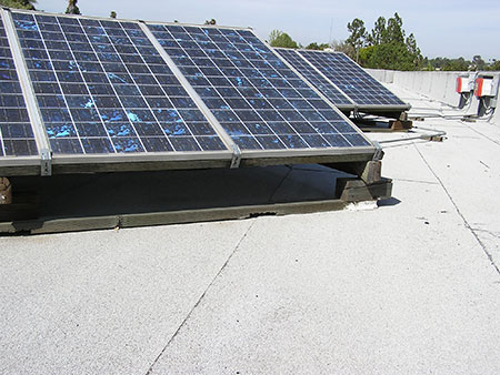
Photo 2. Wooden module support structure glued to roof and modules secured with bent framing brackets
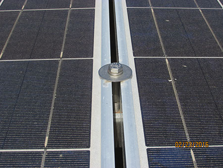
Photo 3. Fender washers used to secure the modules
Since those early “wild west” days, manufacturers have developed rather robust support structures for these now common multi-megawatt projects. The structural steel support structure for the modules consists of hundreds of thousands of connections. Some with high-strength bolts or fabricated brackets (either welded by hand or by robotics). Some utilize connections not commonly associated with normal building construction. At a recent project, the engineered design utilized a press-on fastener commonly found in airplane and truck manufacturing. Because this type of fastener is not recognized by any ASTM standard (A490 or A325), verifying for the suitability of the connection and testing the fastener to the appropriate ASTM can be a challenge, but is extremely critical for wind loading design. Hammering out these alternative methods of construction early on will help streamline the plan review process.
Additionally, two new UL Standards were ANSI-approved last year. UL Standard 3703 discusses Solar Trackers. UL Standard 2703 addresses several critical areas such as mounting systems & devices, clamping/retention devices, and ground lugs for use with flat-plate PV modules and panels. Manufacturers can now apply these safety standards to the design and thus produce appropriate and safe support structures that may also serve as the bonding means.
This article will focus on the details of large-scale support structures for PV and some of the unique challenges for those who build and inspect these large PV projects.
The Array
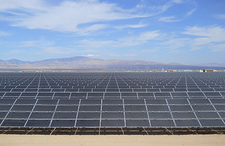
With large scale PV, inspecting the array can be challenging due to the enormous size of the project and the hundreds of thousands of connections to verify (see photo 4). Take for example a recent project, where if we placed all of the project’s modules (1,717,920) end to end, the distance would stretch from Los Angeles to Charleston, South Carolina. Just thinking about all the walking I did while inspecting that project makes my feet hurt.
Photo 4. Bolted connections require inspection
Now for the meat of any PV project, let’s talk about the modules themselves. Starting with the glass modules, thin-film technology typically uses a rubber grommet mounted in a bracket to capture and hold the glass. Crystalline & multi-crystalline technology will use aluminum frames to hold the module laminate using various methods of attachment to the support structure, such as:
- bolted connections to the module frame
- bolted connections with clamps to secure and hold modules
- stainless steel rivets
- roll-in panel cartridges
- proprietary aircraft fasteners
If this support structure is also used as the bonding means for the system, all of the materials used to hold, secure and bond the modules are required to be evaluated by an NRTL using UL 2703 and UL 3703 for trackers and UL 1703 listing/certification for the modules.
Another important point—Reading the installation instructions is extremely important. At a recent project, one of the connection plates used as the bonding means could not be installed correctly because the screws would snap off due to the excessive screw gun torque required for installation. After further review, it was determined that the component could not be properly installed per the installation instructions. During the NRTL review for the original listing/certification, it was discovered that this component arrived at the lab pre-assembled; thus, it was never verified and/or duplicated in the lab to establish repeatability for the assembly. This required a field evaluation and remediation with thousands of listed/certified bonding jumpers to ensure a safe installation.
In the following situations, you will need to evaluate and determine which connections require additional bonding jumpers and the size required:
- The support system is not listed
- The support system is not certified and/or operates over 1000 volts
- A gap has been identified in the rack that requires additional bonding based on the location of the conductive materials likely to become energized
For sizing, you can use the Tables located in Article 250 of the NEC. However, be careful because UL 2703 Table 9.1 is unique (and differs from the NEC) regarding conductor size and screw engagement. For example, according to UL 2703 Table 9.1, a circuit operating at a maximum of 15 to 90 amps would require a minimum 8 AWG bonding conductor. NEC Table 250.122 allows several smaller size copper conductors within this range. Additionally, Section 2703-9.4 says “if the bonding means depends upon threaded fasteners, two or more screws each with at least a (one) full thread, or two full threads of a single screw shall engage the metal.” NEC 250.8 only recognizes the two thread engagement. These are slight modifications that differ from the NEC and something to keep in mind during those discussions.
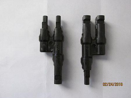
Photo 5. DC PV splitter
The next item of concern relates to adapters and splitters used within the array. The adapters are used to transition from one manufacturer’s PV connector to another manufacturer’s PV connector. As an example, an Amphenol female connector directly joined to a male MC-4 connector has never been tested, listed or certified as an assembly. Several manufacturers have listed/certified jumpers available to make this transition. See the UL White Book product category QHZS for additional information. Splitters are also used to parallel single strings in these large systems and are not listed/certified (see photo 5). And depending on your comfort level, you may need a field evaluation to determine compliance with UL 9703 for this 1000-volt connection (or future 1500-volt). You might say, what’s the big deal? We’ve been doing this for years. However, it’s important to remember that some of these PV connectors/splitters may only be recognized components (some have no markings at all and are unlisted) and the current/voltage ratings vary drastically. Making the mistake of allowing a 16 amp 600-volt connector on a 35 amp 1000-volt circuit could create an unscheduled event. A 1000-volt series circuit at 20 amps during the day is extremely dangerous, especially when the switch (i.e., the sun) is 93 million miles away. The only thing that will turn that off is when the sun goes down, or the equipment becomes shaded from the sun. The author has seen DC thermal runaways due to incorrect terminations; the contractor normally allows the event to continue until the sun goes down.
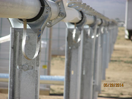
Photo 6. Horizontal axis isolated from vertically driven pile
Regarding trackers during your review, some systems will have an insulating bushing made of hard UV resistant plastic which isolates the horizontal axis of the tracker from the vertically driven pile (support structure). Due to the close proximity of exposed cabling (1 kV & 35 kV), which can be attached to the structure, trenched underground or installed in cable trays, additional bonding may be required for safety (see photo 6). These flexible bonding straps should be listed/certified to UL 2703. Hammering out these details early on in the plan review process will avoid project delays, and contractor anger and discontent, which the AHJ should always try to avoid. Proper planning upfront will always help things run smoothly and on time, which is always the goal of the AHJ.
DC Cabling and Harnesses
The DC cabling and harnesses associated with these systems are usually 2000-volt rated PV wire. Manufacturers are capable of providing 1000-volt rated PV cable so be careful if your system operates at 1500 volts DC. The challenge for the installer is supporting all of the exposed cabling (see photo 7). The support system may be comprised of cable tray or proprietary trays, or it may be supported on the rack by UV rated cable ties. Article 690 provides no guidance for supporting exposed cabling that is run horizontally along the frame of the support structure. However, since most cabling is dual rated USE-2, Article 338.10(B)(4)(b) can be used and references Article 334.30 for securing and support. If the installer is using cable tray systems, then Article 690.31(C) can be referenced for the securing and support. Another important issue when using cable tray is regarding bonding of the tray system to the support structure (see photo 8). These jumpers will need to be listed to UL 2703 and/or UL 3703 (if a tracker) because the cable tray is now used as the bonding path for the system.
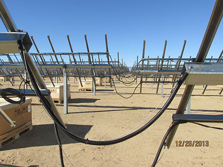
Photo 7. Cable management is imperative for the life of a tracker
Photo 8. Listed UL 2703 bonding jumper
If thin-film technology is deployed at your site, you will have DC harnesses with inline fuses to parallel the single strings before reaching the DC combiners. These harnesses should be listed to UL 9703. Future installations may eliminate DC combiners altogether, which could increase these harnesses to single runs of 500 kcmil or larger conductors with inline DC fusing. Make sure to check the markings on the harnesses, fuse size, voltage ratings, etc. (see photos 9A, B, C, D). It is strongly suggested to check everything when it arrives at the site to avoid multiple trips to the field. At one recent project, one fuse holder was found with the incorrect rating. After further investigation, we found several other discrepancies regarding missing NRTL labels, incorrect fuse markings, and some items with no markings at all. This created a situation where two NRTLs and the manufacturer had to resolve the issue and replace many of the harnesses.
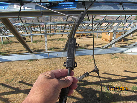
Photo 9A. DC PV harness
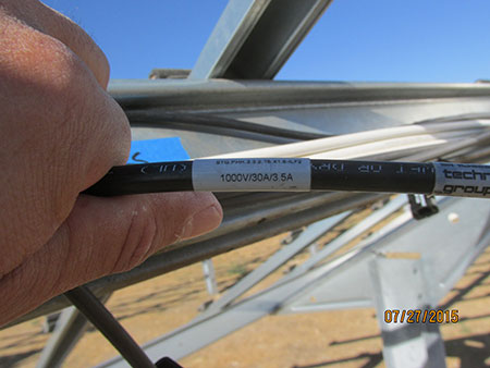
Photo 9B. DC harness with correct markings
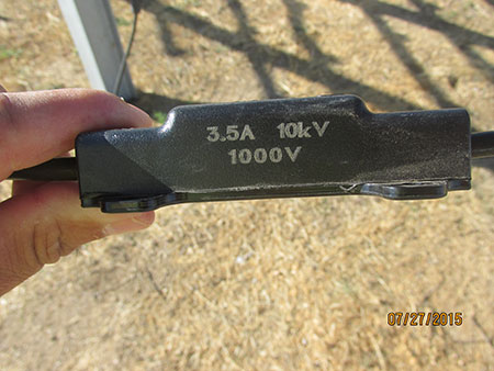
Photo 9C. Fuse holder with proper markings
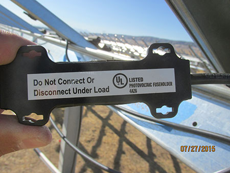
Photo 9D. Fuse holder with proper markings
Special Inspection
As mentioned in my January/February article regarding special inspection (SI), the array may have all or one or two of the Chapter 17 International Building Code (IBC) requirements requiring SI. Over the past 5 years, the author has encountered High-Strength bolting and deeply driven piles at every project. For special inspection of HS bolts, Chapter 22 (Steel) of the IBC Section 2204.2 refers the reader to Chapter 17 Section 1705.2.1 which refers to the American Institute of Steel Construction (AISC) for the inspection requirements. The AISC Section 16.2.2 discusses the importance of proper storage of fastener components because the manufacturer may apply various coatings to facilitate manufacture/installation and prevent corrosion. This involves the:
- storage of HS bolts in closed containers to protect from dirt and corrosion
- storage of the closed containers in a protected enclosure
- removal of HS bolts from protected storage (only as necessary)
- prompt return of any unused HS bolts to the protected storage
If these HS bolts become dirty, rusty, or altered from their original condition, this may affect the pretension installation (torque value) required. Also, A325 galvanized bolts must be used with DH galvanized lubricated nuts (only the nuts are lubricated see photo 10). The lubrication shall comply with ASTM-A563 (which requires all galvanized nuts to be lubricated) and is always a wax-based lubricant, which is clean and dry to the touch with dye added to assist with identification. A490 HS bolts used outdoors are only available with zinc/aluminum inorganic coatings with a similar nut. Galvanized bolts and A490 bolts cannot be reused in any case. The inspection for the installation of HS fasteners is periodic or continuous, depending on the method of tensioning. Additionally, don’t forget that the SI for HS fasteners starts when the materials arrive at the job site. And depending on the method of tensioning, the tools (torque wrenches) used may be required to be verified at the start of each shift. This is just a partial list of duties for the SI. Work with your team to develop a process that verifies compliance to ensure a safe code-compliant installation. Refer to AISC-16.1-179 (14th edition) for the following:
- Inspection requirements
- Tables N5.6-1 Inspection Tasks Prior to Bolting
- Table N5.6-2 Inspection Tasks During Bolting
- Table N5.6-3 Inspection Tasks After Bolting
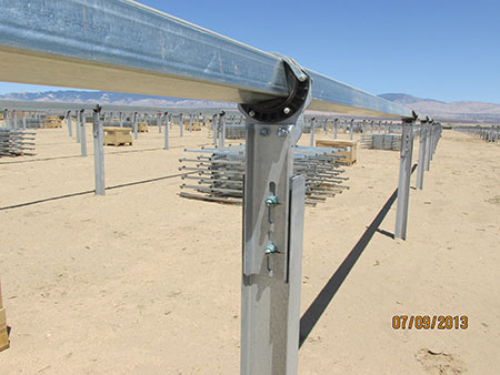
Photo 10. Green (waxed) A563 nuts are lubricated with A325 bolts that require SI
For SI of the driven pile, the inspector should gather all shipping documentation for the structural steel as the material arrives. This saves time and streamlines the inspection process, especially when multiple trucks deliver materials daily. If the materials and accompanying documentation are not inspected when taken from the truck, some of the documentation can get lost. Just take a look at photo 11A. It’s easy to see how this can happen. Failure to track and monitor documentation with the materials creates a situation where the materials are unidentifiable, and additional testing may be required per the IBC. Either that or replacements will need to be shipped to the site. At a recent project, the first 40K piles arrived with no inspection and created extra work for everyone. We spent weeks tracking down the manufacturer’s certifications and matching individual steel pile heat numbers to the documentation (see photo 11B). Proper planning and collaboration between the inspectors and the installing contractors early on can alleviate many of these headaches.
Photo 11A. Daily semi-truck deliveries can seem to be endless and overwhelming
Photo 11B. Every one of these piles had to be visually verified because it was never inspected when it was taken off the truck – don’t let this be you.
Once the rack installation starts, the SI inspector shall be present for the entire operation depending on the inspection frequency required by Chapter 17 IBC. One common occurrence is pile refusal. This is normally due to unknown soil conditions (maybe large rocks) which prevent the pile from penetrating the lower surface of the soil and reaching its required depth. The contractor should have a remediation plan, which could involve drilling a pier and setting the pile in high strength concrete. Or another possible option that can be used when the amount of force to drive the pile has made the top portion of the steel unusable (bent and distorted), you can weld and splice a new piece, which requires SI for the welding and the new materials being introduced into the structure. Refer to Chapter 17 IBC and AISC-16.1-174 (14th Edition) for the following:
- Inspection of Welding
- Table N5.4-1 Inspection Tasks Prior to Welding
- Table N5.4-2 Inspection Tasks During Welding
- Table N5.4-3 Inspection Tasks After Welding
Additionally, don’t forget that any underground cables in trenches will have compaction requirements usually buried in the geotechnical report. The report will give a specified lift, the amount of material in inches, and the required compaction for each lift. As an example, if the report called out a 42-inch deep trench with a specified lift amount of 8 inches at 90% compaction, then we will most likely have 5 inspections for that trench. The most common device used is calibrated Nuclear Gauge for Density and Moisture Soil Testing (see photo 12). Remember, soil thermal properties for underground medium/high voltage cables are an important part of the overall design. The soil is between the heat flow path of the cable and the outdoor environment. A resistance to this heat flow path, such as an air pocket, can cause a hot spot in the feeder cable, which will eventually lead to an insulation failure. The fill must be compacted tightly to minimize air spaces around the cables. Sometimes the installing contractor may need to import materials because the soil contains too much organic matter (like farm land) causing high thermal resistivity. Starting the conversation early with your team members will not only assist with your inspection requirements, but possibly save the contractor from additional rework and unscheduled power events due to unforeseen soil conditions.
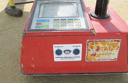
Photo 12. Nuclear Gauge for Density and Moisture Soil Testing (note calibration date)
Summary
As you can see, inspecting these multi-megawatt systems can be challenging and time-consuming; however, communicating with the engineers, contractors, electricians and special inspectors early on before the project begins is critical in communicating the expectations related to the inspections and the equipment installation. I cannot stress the importance of good communication and the damaging results of poor communication when it comes to these large projects. At one project, while inspecting forty-four 35 kV transformers, I asked the cable splicer to pop a boot at one of the transformers so that I could see the crimp termination (see photo 13). As you can see from the photo, the contractor used a termination for stranded aluminum. However, the conductor was compact aluminum (OOPS!) one size too big. Because of this, the contractor had to go back and replace over 130 BOL-T connectors. If someone from their team had included the inspector in the conversation in the beginning, there’s a good chance that issue could have been avoided. As it was, a violent event was likely prevented from occurring. In that situation, an event could have injured and/or killed somebody. The inspector’s role is critical in ensuring a safe installation.
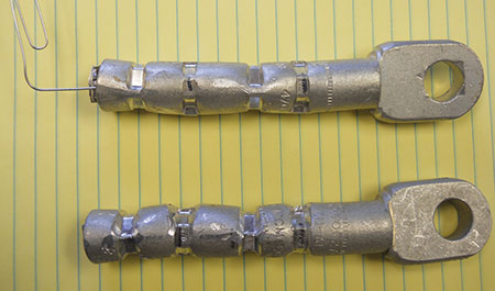
Photo 13. Improper 35kV terminations
I have only touched on some of the many inspection challenges regarding these large systems. However, these systems, if properly, built, inspected, and commissioned, will operate safely and efficiently for decades with limited maintenance and unscheduled power events.
If this article has generated any additional questions and/or comments, please contact the author by phone 619-318-7310 or email at shinspections.inc@cox.net