To start with let’s look at the different types of ground fault protection. The Canadian Electrical Code Part I (CE Code) defines ground fault protection as: “a means of detecting and interrupting a ground fault current at a level less than the current required to operate the circuit overcurrent device”. Although ground fault circuit interrupter represents a very specific type of ground fault protection (and it is defined separately), in general, ground fault protection can be in the form of ground fault circuit interrupter of the Class A type that interrupts the circuit within a predetermined time with a ground fault current between 4mA and 6mA intended for protection of people and not equipment; ground fault circuit interrupter with trip settings above 6mA typically 10mA and 30mA is described in the CE Code as for protection of specific equipment; and ground fault protection intended for protection of electrical distribution equipment. The remainder of this article will focus on ground fault protection requirements for distribution equipment.
Electrical distribution systems can be ungrounded, impedance grounded, or solidly grounded. Systems that have a maximum voltage-to-ground that does not exceed 150V, or systems that incorporate a neutral conductor are required by the CE Code to be solidly grounded. One exception is a system that incorporates a neutral conductor with a maximum voltage-to-ground that does exceed 150V; these systems can be impedance grounded.
Circuits of solidly grounded electrical systems are to be installed in accordance with the requirements for ground fault protection in CE Code Rule 14-102. Subrule (1) requires systems rated more than 150 volts-to-ground, less than 750 V phase-to-phase and 1000 A or more to be provided with ground fault protection that will, in the event of a ground fault de-energize all normally ungrounded conductors of a faulted circuit that are downstream from the point or points marked with an asterisk in Diagram 3.
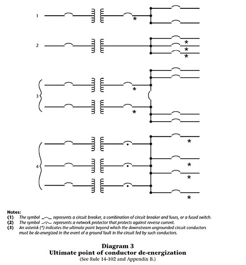
In Canada, these requirements were first introduced into the 1972 Ontario Electrical Safety Code. The rule was adopted into the CE Code in the next edition dated 1975. Since the introduction of this rule, the changes have been editorial. As an example, Diagram 3 was originally Table 49 with the same content.
Unlike the National Electrical Code, Articles 210.13, 215.10, and 240.13 Subrule (1) of CE Code Rule 14-102 require ground fault protection for circuits of solidly grounded systems rated 150 V or less to ground and 2000 A or more. This means a 208Y/120V 2000A circuit requires ground fault protection.
Subrule (2) of Rule 14-102 requires the maximum setting of the ground fault protection to be 1200 A and the maximum time delay to be one second for ground fault currents equal to or greater than 3000 A. Subrule (8) recognises ground fault schemes where two or more protective devices in series are used for ground fault coordination. Where necessary to obtain the desired coordination for these configurations the upstream ground fault protective device settings are allowed to exceed the maximum ground fault settings, provided that the final downstream ground fault protective device in each circuit conforms to the requirements of Subrule (2).
Subrule (3) of Rule 14-102 provides details on the ampere ratings of the circuits that require ground fault protection. The ampere rating of the circuit is considered to be the ampacity of the main conductor on the secondary of the transformer shown in Item 2 of Diagram 3, the highest trip setting of the circuit breaker, or the rating of the largest fuse that can be installed.
Types of equipment ground fault protection
Three types of distribution system ground-fault protection include bonding jumper, zero sequence, and residual ground-fault protection.
Bonding jumper ground-fault protection utilises a current transformer encircling the system bond jumper. Sufficient current through the system bond jumper will initiate the ground fault protection. Where the neutral is grounded at both the supply transformer and the distribution equipment, a current transformer is not required, provided that the maximum pickup setting of the ground fault relay does not exceed 1000 A as detailed in Subrule (7) of Rule 14-102.
Zero sequence ground fault protection consists of a current transformer that encircles the system neutral and all the circuit phase conductors within the distribution equipment. During a fault to the bonding system, all the return current will not flow through the zero sequence current transformer resulting in operation of the ground fault protection.
Residual ground fault protection is very similar to the zero sequence ground-fault protection. The main difference is that the ground fault relay is used with individual current transformers for the neutral and each circuit phase. The vectorial sum of the neutral and circuit phase currents is used to identify a fault to the bonding system and operate the ground fault protection.
The location of the system bond jumper and the ground electrode conductor is very crucial. The system bond jumper and the ground electrode conductor connection must be on the supply side of the zero sequence or individual residual ground fault current transformer.
Ground-fault protection installed on a system that has backup generation.
Generators can be supplied with a bond jumper installed between the neutral and the generator frame, and others are supplied without the bond jumper. When a generator is the source of a solidly grounded system, and it supplies a building distribution system, precautions must be taken to ensure the neutral of the grounded system created by a generator is grounded at one location only. As an example, if the system created by a generator has the neutral grounded at the generator, the power supply source-transfer device used will need to have the generator neutral isolated from the building system neutral during normal operation (4-pole transfer device for a three-phase system).
Another installation that could cause issues is wiring from one building to another when the main supply has ground fault protection. Rule 10-208 from the 2015 CE Code allows the system neutral to be grounded in the second building. When the distribution equipment at the main building is equipped with ground fault protection, grounding of the system in the second building could defeat operation of the ground fault protection.