
The most routinely encountered transformer installation is likely the common three-phase 480/277 volts (V) to 208/120 V wye dry-type transformer supplying a panelboard. Many field electricians, design professionals, and inspectors struggle with these installation requirements. Electricians and Inspectors who feel very confident with installing and inspecting electrical services will sometimes be far less comfortable when dealing with grounded-type transformers installed on the load side of a building’s service disconnecting means. Let’s look at the basics of a grounded 480/277 V to 208/120 V wye-type transformer supplying a panelboard in a typical retail or office space.
Location, location, location
The dry-type grounded transformer at or under 112.5 KVA with the system bonding jumper installed in the transformer enclosure that we are addressing in this article must be placed in a location that provides working clearance, safe distances from combustible materials, ready access, and proper heat dissipation. Where do we go for these requirements? Let’s start with 2017 National Electrical Code (NEC) Article 450.
Is the transformer readily accessible as required by NEC Section 450.13? The general rule of this section is that the transformer must be readily accessible. However, some significant additional permissions to this rule exist. A transformer that is 1,000 V nominal or less may be located on walls, columns, or structures in the open and does not require ready access. [See Section 450.13(A).] A transformer not in excess of 50 KVA may be located in a hollow space of a building—such as in a suspended ceiling—and does not require ready access. [See Section 450.13(B).] So, do we have the proper location for our transformer? Well, not yet. We still must address the issues of heat dissipation, working clearance, and nearby combustible materials.
Transformers must be ventilated such that the full load heat losses are disposed of in a manner that does not cause heat rise in excess of the rating of the transformer. [See Section 450.9.] Transformers with ventilated openings shall not have these ventilated openings blocked by walls or other obstructions and must be marked with the required distance between the transformer ventilation openings and any adjacent obstruction. [See Section 450.11.] Electrical equipment rooms which contain transformers are often provided with thermostatically-controlled fan units to assist with heat dissipation. Transformers that are not properly ventilated may operate less efficiently with a shorter lifespan.
wDry-type transformers rated 112 ½ KVA or less are required to be located at least 12 inches from combustible materials per Section 450.21(A). The exception to this rule is: the 12 inches minimum clearance to combustibles does not apply to transformers 1,000 V or less that are completely enclosed except for ventilation openings—which is the type of transformer we are addressing.
Now, let’s explore working clearances. NEC Section 110.26 requires electrical equipment that is likely to require servicing, examination, or adjustment while energized must be provided with the working clearances of this Section, and the working clearance shall permit at least a 90-degree opening of doors or hinged panels. This section requires the width of the working space to be 30 inches or the width of the equipment, whichever is greater, and the height of the working space to be 6 feet 6 inches or the height of the equipment, whichever is greater. Section 110.26(A)(4) addresses limited access working spaces such as may be encountered in a suspended ceiling.
How about the depth of the space? The supply voltage of the transformer is 480/277 V. The voltage to ground of any phase of the supply conductors accordingly is 277 V. The requirements of Table 110.26(A)(1) specify 3 feet of clearance from a transformer with exposed live parts on one side and no live or grounded parts on the other side of the work space; 3.5 feet if we have grounded parts opposite the transformer, and 4 feet if we have other live parts opposite the transformer. These measurements are taken from the transformer enclosure outward. We are now ready to set the transformer in place.
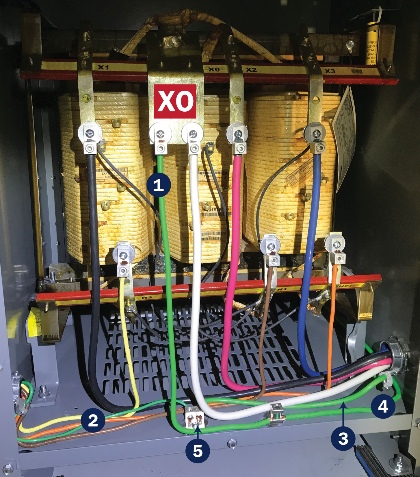
2. Equipment grounding conductor
3. Supply-side bonding Jumper
4. Grounding electrode conductor
5. Terminal connection to enclosure
Grounding & bonding
At a grounded-type wye transformer, we install a system bonding jumper at a location from the transformer to the first disconnecting means on the secondary side. This system bonding jumper connection, when made in the transformer enclosure provides a path from the center point of the wye configuration via the x/o terminal to a terminal bar in direct contact with the normally non-current-carrying metallic enclosure of the transformer. This terminal bar is used to connect the grounded conductor, supply-side bonding jumper, the normally non-current-carrying metallic enclosure, equipment grounding conductor(s), the grounding electrode conductor, and possibly a metal water pipe bond (we will discuss this later). As of 2014, NEC Section 450.10(A) requires a terminal bar be provided for these connections, and the bar is not to be installed over ventilation openings.
We may also choose to connect the system bonding jumper at the first disconnecting means on the secondary side of the transformer. When the system bonding jumper connection is made at this location the grounding electrode conductor connection will also be made at this point. This type of connection is somewhat less common, and we will discuss this option another time.
At a typical 480/277 V to 208/120 V wye-type transformer supplying a panelboard, we would generally have five conductors supplied from the transformer and transformer enclosure to the panelboard. This would consist of three ungrounded phase conductors, one grounded neutral conductor, and a supply-side bonding jumper. This supply-side bonding jumper is often incorrectly identified as an equipment grounding conductor leading the installer to improperly use NEC Section 250.122 to size the conductor when NEC Section 250.102 or a non-flexible metallic raceway must be utilized. Using Section 250.122 will generally result in an undersized conductor thus limiting the ability of the supply-side bonding jumper to carry enough current to quickly clear a fault. The equipment grounding conductor at this type of transformer is routed with the primary side supply conductors to the transformer enclosure and is sized per NEC Section 250.122.
The grounded neutral conductor will be connected to a terminal bar that does not contact the metallic panelboard enclosure or any grounded metallic parts after connection to the system bonding jumper in the transformer enclosure. Some will refer to this as “floating the neutral” in the panelboard enclosure. (Not a Code term). The neutral and other grounded conductors of the branch and feeder circuits supplied from this panelboard are connected to the grounded terminal bar inside the panelboard enclosure. The supply-side bonding jumper will be connected to a terminal in contact with the metallic panelboard enclosure, and the equipment grounding conductors of branch circuits and feeders supplied by the panelboard will be connected to this terminal bar. These grounded and grounding connections at the panelboard supplied by the transformer are done in much the same way as a typical feeder supplied panelboard.
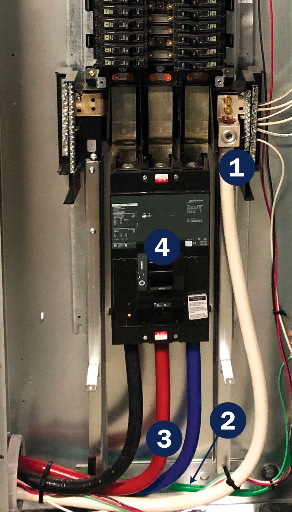
2. Supply side bonding jumper
3. Secondary conductors
4. Secondary conductor overload protection
The grounding electrode conductor(s) in this application is routed from the transformer terminal bar where the system bonding jumper is connected to the grounding electrode. Making a connection to the metal in ground support structure (we formerly referred to this electrode as the metal frame of a building or structure) is likely the most common means of providing an electrode. The 2017 NEC now permits us to connect to the building grounding electrode system rather than mandating an order of precedence beginning with building steel or the nearest available effectively grounded water pipe and then to other types of electrodes if one of these is not available. If we use a connection to the metal in a ground support structure, then we must remember to bond the water pipe in the area served by the transformer. Wait a minute, didn’t we already bond the metal water pipe at the service? Yes, we did. However, we have created a new separately derived system. Current produced via the transformer will try to return back to the midpoint of the wye transformer windings via the x/o tap of the transformer.
Bonding the water pipe in the area served by the transformer as required by NEC Section 250.104 (D)(1) will provide a low impedance path for any objectionable currents that may find their way onto the waterpipe and any faults that may occur as a result of contact with the waterpipe. We are permitted to use a bonding jumper from the metal in ground support structure to the waterpipe(s), meaning we only need to connect to the transformer terminal strip once, if done in this manner. If we use a connection to the waterpipe as our connection to the electrode system, this additional waterpipe bonding step is not required.
Transformer disconnecting means
A disconnecting means must be located within sight of the transformer. To be within sight, the transformer and the disconnecting means must be visible from each other and not more than 50 feet in distance. If the disconnecting means is not located within sight of the transformer, the disconnecting means must be lockable in accordance with Section 110.25 and the transformer field marked with the location of the disconnecting means. The breaker supplying the transformer primary is often used for this purpose. The question that is frequently asked is, “Would a properly rated unfused safety switch be suitable for this disconnecting means?” Yes.
Primary side ungrounded conductors
The primary side protection for the transformer in this installation is not more than 125 percent, thus not requiring secondary protection. [See Section 450.3 (B).] A 45 KVA wye 480/277 V transformer primary would require a conductor ampacity of 54.19 amperes at 125 percent totaling 67.73 amperes. (45,000 /830.4 = 54.19 x 1.25 = 67.73) Our conductor size would be based on this number. Note 1 to Table 450.3(B) allows us to round up to the next standard size of 70 amperes for our overcurrent device protecting the transformer, and Section 240.4(B) permits us to round up our overcurrent protection of the conductors on the primary side also to the next standard size of 70 amperes.
Secondary side ungrounded conductors
The transformer secondary side conductors supplying our panelboard are sized based on a few factors. The first is the load served by the panelboard supplied by the transformer secondary. It should come as no surprise that the conductors must be sized large enough to supply the connected load. Additionally, these conductors must be a minimum size that may be larger than the load served. This is a basic tap rule concept. The secondary conductors need to be of sufficient ampacity to carry enough current under a ground fault or short-circuit condition to open the overcurrent device on the supply side of the transformer primary.
When these conductors are not longer than 25 feet, the conductors must be a minimum size of 1/3 the size of the primary side overcurrent device multiplied by the voltage ratio of the primary to secondary sides of the transformer. A 480 to 208 is a 2.3 ratio. For a 45 KVA transformer the size of the primary side overcurrent device is permitted to be 70 amperes. The ampacity of the load side conductors must be a minimum of 1/3 the value of the primary side overcurrent device—or 23.34 amperes in this case—multiplied by the primary to secondary voltage ratio of 2.3. The secondary conductors accordingly must have a minimum ampacity of 53.68 amperes. This is essentially the 25 feet tap rule taking the voltage ratio into consideration. [See Section 240.21(C)(6).] If the secondary side conductors are 10 feet or less the rating of the overcurrent device protecting the primary multiplied by the primary to secondary voltage ratio shall not exceed 10 times the ampacity of the secondary conductors. A 45 KVA transformer protected on the supply side with a 70-ampere circuit breaker multiplied by the ratio of 2.3 would result in the secondary conductors having a minimum ampacity of 16.1 amperes or 1/10 the size of the primary overcurrent device after the voltage ratio is applied. This is very similar to the standard 10-foot tap rule.
While there is a minimum size for secondary conductors as we have discussed, there is no maximum size other than what we may encounter for terminal sizes. One should keep in mind that transformers operating in excess of their rating will result in greater heating and a shorter lifespan. For the 45 KVA transformer we discussed, the optimal load for the secondary conductors would not exceed 125 amperes.
Conductors are permitted to be connected to the transformer secondary without overcurrent protection at the secondary when the transformer is provided with supply side protection not exceeding 125 percent. The overload protection of these conductors is provided at the termination of the secondary side conductors. [See Section 240.21(C).] The overload protection must not exceed the rating of the conductors and we are not allowed to round up to the next standard size overcurrent device as otherwise permitted in NEC Section 240.4. [See Section 408.36 for panelboard protection.]
The preceding text is based on the installation of the common 480/277 V to 208/120 V wye dry-type transformer at or below 112.5 KVA with the system bonding jumper at the transformer. This installation is likely the most common type transformer arrangement found in commercial office and retail spaces. This is but one type of the many possible transformer configurations that may occur. A sound working knowledge of these basics will prove invaluable to understanding the installation requirements of transformers of any voltage or phase arrangement.